Section 360-080-102
2
1. GENERAL
1.1 Document Purpose
This document provides turn up and acceptance test procedures for the 360-80 Intelligent Channel Bank (ICB).
2. VERIFYING ELECTRICAL CONNECTIONS
2.1 Initial Installation Notes
Step Action
1. Shelf must already be mounted per documentation.
2. Unit must already be wired for power from a fuse panel. Power should not be applied at this time.
2.2 19-inch and 23-inch Bays
If modules are already installed in the ICB, remove them before testing.
Step Action
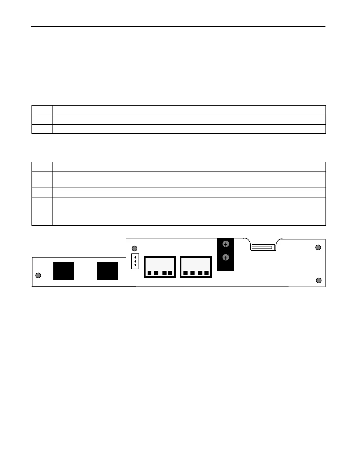
1. Connect the audio and visual alarm leads to the removeable connector on the back of the ICB shelf.
Reference the Shelf documentation for the proper procedure. Figure 1 displays the shelf rear panel.
2. Apply power to the shelf.
3. Locate the power terminal block on the rear (see Figure 1) of the ICB. Using a voltmeter connect the −
(common) test lead to −48VR screw terminal. With the + test lead, measure the voltage at the −48V
terminal. The voltage should be between −44 and −56 VDC. If voltages are not correct, inspect wiring
for proper polarity, and/or check power source for proper settings (or output) and correct as required.
J1 J2
IN OUT
AUD VIS
CCLK
TERM
CCLK
ALM
FUSE 4A
−48VR
−48V
OUT
IN
PRI
+
+
+
+
T1/E1
TERM
NETWORK
MGMT
Figure 1. 360-80 Terminal Block
3. SYSTEM TURN-UP
Use the following steps to turn up the system. Only the T1 controller unit (T1-S) should be installed as instructed.
Figure 2 displays the T1 Controller Unit Front Panel.