Section 360-080-102
3
Step Action Verification
1. Insert the T1-S into the ICB. Do NOT connect the
T1 to J1 at the rear of the T1-S.
The green LED on the T1-S should be lit, indicat-
ing that the T1-S is powered.
When first plugged in, the AR, AY, TP and LP
LEDs on the front panel of the T1-S will light and
then extinguish. Approximately 5 seconds after
power is applied, the 4 LEDs will flash simulta-
neously (LED test), indicating that the T1-S is ini-
tializing.
Since a T1 line is not connected, approximately
2.5 seconds after the flashing LEDs have extin-
guished, the red AR LED will light, followed by the
yellow TP LED, indicating that no T1 signal has
been detected and trunk processing is in progress.
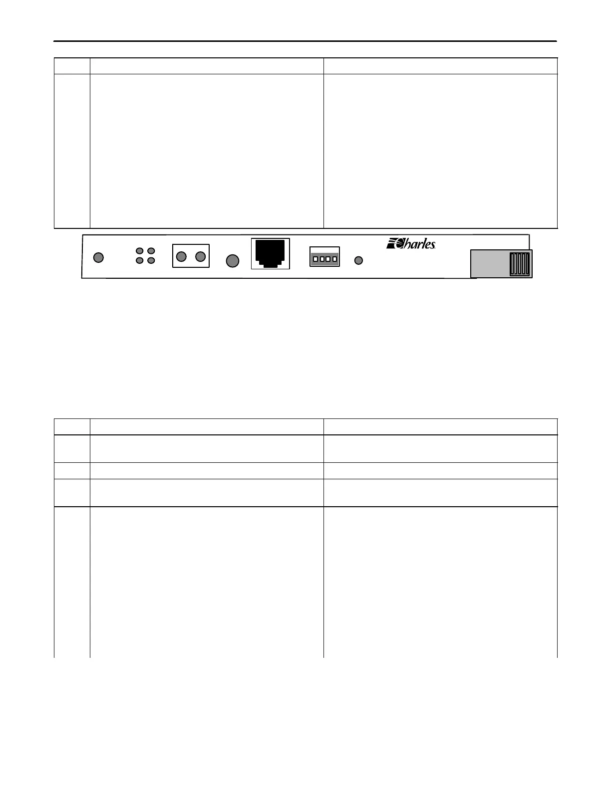
T1
3603−81
AR AY
TP LP
MON
RCV XMT
ACO
MGMT
ADDRESS
ID PWR
+
Figure 2. T1 Controller Unit Front Panel
4. CONTROL VERIFICATION
To get the information displayed as shown, the control verification tests should be done with alarms active.
Control verification is done using the NMS or a craft terminal.
4.1 Control Verification Using a Craft Terminal
Refer to the Craft Terminal documentation while performing the following steps.
Step Action System Response
1. Connect the VT100 terminal emulator to the
MGMT jack on the front of the T1-S
2. Press <Enter> to activate the T1-S Login prompt appears.
3. Login with the user name piad and press
<Enter>
Password prompt appears.
4. Type 1234 as the password and press <Enter> The following information should be displayed in
the main menu:
Primary T1 Module Plugged
Halfsize Module Unplugged
Channel Card 1 Unplugged
Channel Card 2 Unplugged
User Administration
Card Inventory Data
SNMP Community Table
Trap IP Table
IP Address/Subnet Mask/MAC Gateway
Address Message
Logout