Do you have a question about the Cheminees Philippe RADIANTE 700 and is the answer not in the manual?
Cheminées Philippe Australia & Wignells of Melbourne disclaims liability for non-compliant installations.
Essential safety information and instructions must be read before installation or use.
Appliance and flue system must be installed to AS/NZS 2918:2018 and building codes.
Mixing appliance or flue components from different sources can cause hazardous conditions.
Check contents, prepare installation site, ensure correct base and safe clearances.
Ensuring adequate air flow for effective burning, especially in tightly sealed homes.
Only approved flue kits should be used; minimum lengths and clearances are specified.
Guidelines on the use and placement of flue bends to ensure proper draft and safety.
Specifies approved materials like hebel blocks, masonry, and concrete for the base.
Lists materials that should not be used for the base or hearth due to safety concerns.
Notes slight variances in dimensions and weight due to handmade nature of fireplaces.
Specifies the heating capacity of the unit in square meters.
Details the maximum average heat output in kilowatts.
Specifies the minimum required height for the flue system.
Provides the weight of the firebox.
Details the certificate of compliance for the unit.
Inspect site, install wall protection, position unit, and assemble damper system.
Install starting collar, flue, triple skin dropper, cowl, and maintain clearances.
Fit internal components and perform a test fire to check flue draw.
Provides standard minimum height of unit and hearth depth dimensions.
Details the minimum width, depth, and thickness for the fireplace base.
Specifies the minimum width, depth, and thickness for the fireplace hearth.
Includes wall, ceiling, glass, and corner clearances for freestanding installations.
Details clearances for Skamotec board, brick/hebel walls, and steel heat shields.
Description of Skamotec board and its properties for wall applications.
Instructions on fixing Skamotec boards and battens using screws and adhesive.
Configuration for ventilation using a 25mm air gap at the top and bottom.
Method for installing concealed external vents for wall ventilation.
Method for installing concealed internal vents for wall ventilation.
Lists and illustrates components for 4.5 meter 9" single and triple skin flue kits.
Diagram illustrating a typical single skin flue kit installation for freestanding units.
Illustrations of various flue system configurations for freestanding installations.
Inspect site, install walls, position unit, and assemble damper system.
Install flue, deflector plate, rockwool, and internal components.
Finish facade, test fire draw, and ensure all steps are completed correctly.
Specifies the minimum height requirements for the unit's base.
Details the minimum depth required for the hearth.
Details the minimum width, depth, and thickness for the fireplace base.
Specifies the minimum width, depth, and thickness for the fireplace hearth.
Defines zones around the unit where heat-sensitive materials must not be placed.
Details materials and clearances for brick/hebel or Skamotec enclosures.
Specifies sizes and placement for air inlet and outlet grilles in the cavity.
Details installation of the galvanised metal deflector plate and rock wool blanket.
Information on fitting ventilation grills for air intake and outtake.
Lists and illustrates components for partial and full masonry inbuilt flue kits.
Diagram illustrating a partial masonry inbuilt flue system installation.
Diagram illustrating a full masonry inbuilt flue system installation.
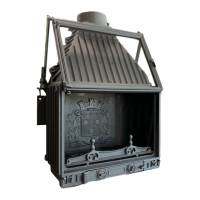
Diagram showing the location of key mechanisms like door lift and air controls.
Explains the operation of primary air and damper controls with open/close states.
Instructions for assembling the smoke gather chamber to the firebox base.
Guide for assembling the counterweight mechanism, including adjustment details.
Instructions and tips for adjusting the damper for optimal performance.
Sequence for fitting internal components like decorative plate, baffle, and grates.
Details on fixing mesh sides for an inbuilt insert with a single window.
Instructions for initial fires, drying time, and managing initial odours.
Guidance on operating the fireplace with the door open or closed.
Information on fuel types, preparation, and storage for efficient burning.
Details on moisture content, types of Australian hardwoods, and their heat output.
A specific caution regarding the maximum weight of wood to load.
Lists essential materials like fire lighters, kindling, and hardwood.
Pre-lighting checks including damper, air inlets, and ash bed.
Step-by-step guide for lighting the fire using the top-down method.
Step-by-step guide for lighting the fire using the traditional method.
Tips for refueling, maintaining fire, and avoiding damage from high temperatures.
General warnings about water use, proximity to heat, supervision, and chimney fires.
Cautions against modification, flammable liquids, fuel storage, and operating conditions.
Guidance on annual cleaning, checks, and protecting cast iron elements.
Instructions for cleaning the fireplace glass panel using recommended cleaners.
Addresses issues like downdraft, lack of heat, and dirty windows with potential solutions.
A comprehensive list of spare parts with designations and codes.
Instructions on how to request spare parts and note serial numbers.
General terms and conditions of the fireplace warranty.
Table outlining standard and extended warranty periods for fireplace components.
Information on obtaining a five-year extended manufacturer's warranty.
Mandatory checklist for installers to confirm compliance with installation requirements.
Fields for installer's name, company, contact number, and compliance certificate.
| Model | RADIANTE 700 |
|---|---|
| Category | Indoor Fireplace |
| Type | Insert |
| Width | 700 mm |
| Flue Diameter | 200 mm |
| Weight | 120 kg |
| Efficiency | 75% |
| Material | Cast Iron |
| Color | Black |