Page 2
THE G746A TOOL
TABLE OF CONTENTS
Description ............................................................................................................................................................................... 2
Specifications .......................................................................................................................................................................... 2
Safety Warnings ...................................................................................................................................................................... 3
Riveter usage ........................................................................................................................................................................... 4
Maintenance and Repair ......................................................................................................................................................... 4
Fill and Bleed Instructions ....................................................................................................................................................... 5
Trouble Shooting ..................................................................................................................................................................... 5
Overhaul .................................................................................................................................................................................. 6
Air Valve ...................................................................................................................................................................... 6
Head Sub-Assembly ................................................................................................................................................... 6
Handle Sub-Assembly ................................................................................................................................................ 7
G746A Pulling Heads .............................................................................................................................................................. 7
Cross Section Drawing ............................................................................................................................................................ 8
Parts List .................................................................................................................................................................................. 9
Exploded View ....................................................................................................................................................................... 10
Declaration of Conformity ......................................................................................................................................Back Cover
DESCRIPTION
The Cherry G746A is a pneumatic-hydraulic tool designed specifically for the most efficient installation of CherryMAX® Bulb,
CherryMAX® “A” wiredraw, and CherryLOCK® “A” wiredraw rivets. This riveter utilizes the straight, offset and right-angle pulling
heads. Refer to the pulling head section for the correct pulling
head part number for the rivet to be installed.
The G746A has a durable metal housing that makes this tool
extremely robust for use in a shop environment.
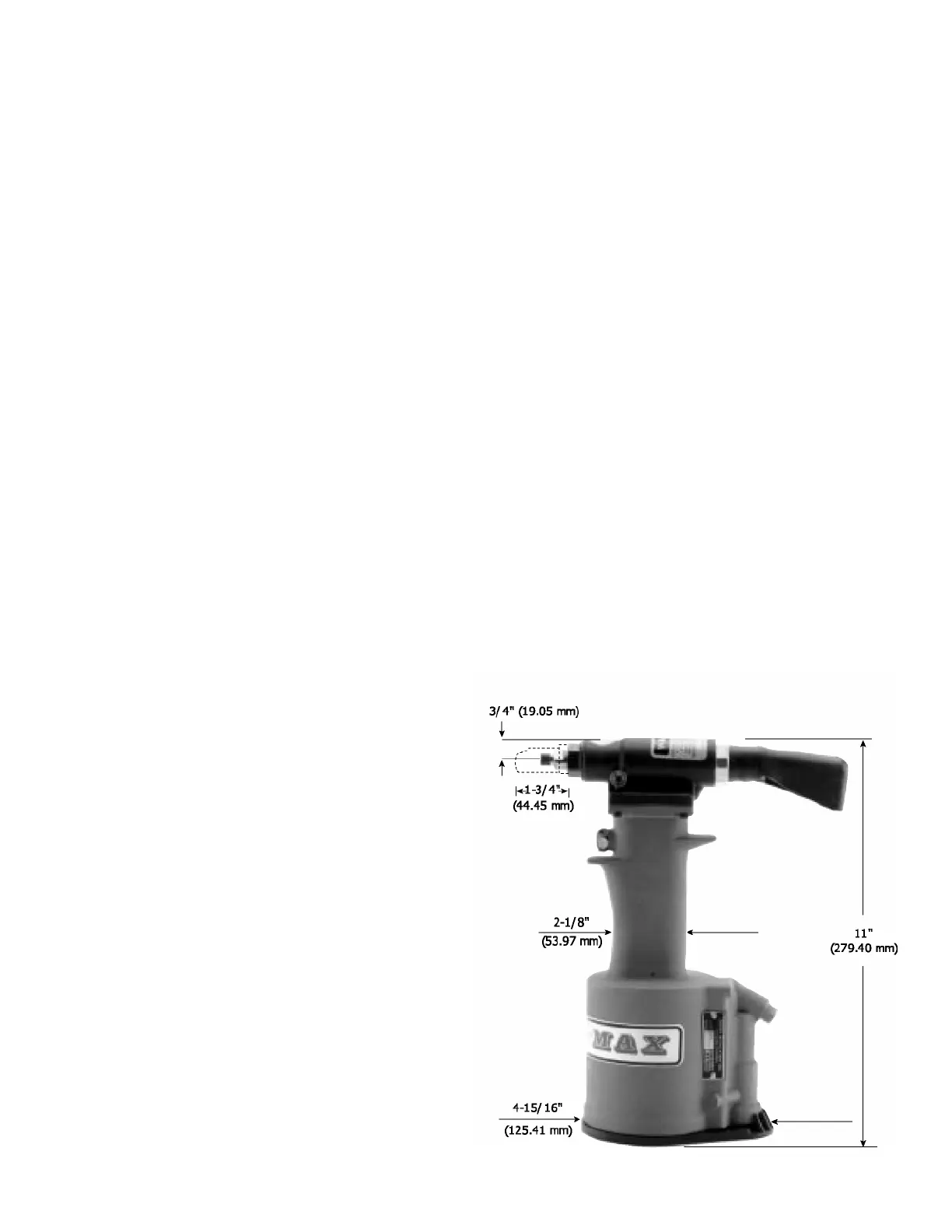
SPECIFICATIONS FOR G746A
Cherry Aerospace (CHERRY®) policy is one of continuous
development. Specifications shown in this document may be
subject to change which may be introduced after publication.
For the latest information always consult CHERRY®.
AIR PRESSURE 90 PSI (6.2 bar) Min. / 110 PSI (7.6 bar) Max.
STROKE .875 inch (22.23 mm)
PULLING FORCE 1850 Pounds (8.23 kN) @ 90 PSI (6.2 bar)
CYCLE TIME Approximately one second
WEIGHT 4 1/4 Pounds (1.93 kg)
NOISE LEVEL 72 dB (A)
VIBRATION 2.5 m/s
2
AIR CONSUMPTION 3.9 CFM (110.5 liters/M) at 20 Cycles per Minute
 Loading...