This document is an operation manual for the Voyager Lathe, a machine designed for precision turning operations.
Function Description:
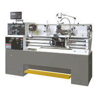
The Voyager Lathe is a robust machine tool primarily used for shaping materials by rotating a workpiece against a cutting tool. It is designed for trained and experienced personnel, offering features for various turning, threading, and feeding operations. The lathe's main components include a headstock, lathe bed, carriage, cross-slide, compound slide, four-way tool post, apron, tailstock, leadscrew, feed rod, and gearbox. It also incorporates a coolant system for efficient operation and a foot brake for safety.
Important Technical Specifications:
- Swing Through the Gap: 508mm
- Distance Between Centres: 1000mm
- Hole Through Spindle: 40mm
- Spindle Nose: D1-4
- Taper in Spindle Nose: MT5
- Spindle Taper Adaptor: MT3
- Number of Spindle Speeds: 12
- Range of Spindle Speeds: 40-1800rpm
- Number of Longitudinal and Cross Feeds: 42
- Range of Longitudinal Feeds (mm/rev): 0.043-0.653
- Range of Cross Feeds (mm/rev): 0.024-0.359
- Number of Inch Threads: 28
- Range of Inch Threads: 4-56 TPI
- Number of Metric Threads: 37
- Range of Metric Threads: 0.4-7mm
- Toolpost Type: 4-Way
- Maximum Tool Size: 16x16mm
- Maximum Compound Slide Travel: 88mm
- Maximum Cross Slide Travel: 170mm
- Maximum Carriage Travel: 950mm
- Tailstock Spindle Travel: 120mm
- Diameter of Tailstock Spindle: 45mm
- Taper in Tailstock Spindle: MT3
- Overall Dimensions: 1900x710x1170mm
- Net Weight: 1200Kg
- Gross Weight: 1300Kg
Usage Features:
- Chuck Preparation: The manual details a specific procedure for safely installing and adjusting the chuck, including supporting it with a wooden block, turning camlocks, inspecting studs, cleaning parts, and applying oil. Index marks on the camlock and indicator arrows guide proper tightening.
- Controls: The lathe features a control panel on the front of the gearbox with a Coolant On/Off Switch, Power Indicator Light, and an Emergency Stop Button. Headstock gear change levers, a leadscrew/feed rod direction lever, and feed/leadscrew selector levers and knobs are provided for precise control over spindle speed, feed rates, and threading operations. A Jog Switch allows for incremental spindle movement.
- Carriage and Tool Post: The carriage, cross-slide, and compound slide offer extensive travel and rotational capabilities (360° for the compound slide), with adjustable gibs for maintaining precision. A four-way tool post allows for mounting up to four tools simultaneously, requiring a minimum of two clamping screws for secure tool installation.
- Tailstock: The tailstock slides on a V-way and can be locked at any position. It features a heavy-duty spindle with a Morse taper #3 and a handwheel for quill traverse. Off-set adjustment screws are available for cutting tapers.
- Feeds and Threading: The lathe supports both inch and metric threading, with detailed instructions on using feed and thread charts, half-nut engagement lever, and threading dial. For metric threads, the half-nuts must remain continually engaged.
- Safety Features: The manual emphasizes the importance of wearing safety glasses/face shields, proper grounding, removing loose clothing and jewelry, keeping guards in place, and maintaining a clean work area. An Emergency Stop Button is prominently located. A foot brake is provided to stop the machine quickly.
- Removable Gap: The lathe features a removable gap section, allowing for larger diameter workpieces. Instructions are provided for its removal and installation, involving taper pins and hex socket cap screws.
- V-Belts: The V-belts can be replaced and adjusted by loosening the motor mount hex nut, removing old belts, installing new ones, and tightening to achieve approximately ¼” deflection with 8lbs of force.
Maintenance Features:
- Lubrication: Critical for the lathe's longevity, the manual provides detailed lubrication instructions for the headstock, gearbox, apron, leadscrew/feed rod, tailstock, cross slide, compound rest, and carriage. Oil reservoirs must be filled to indicator marks, and specific drain plugs are identified for oil changes. Initial oil changes are recommended after the first month of operation, followed by every 12 months. Ball oilers require daily lubrication.
- Cleaning: Before operation, anti-rust oil must be cleaned from machine surfaces using a mild commercial solvent or kerosene, avoiding paint thinners. A thin layer of machine oil should then be applied to bare metal surfaces. The end gear compartment components also require cleaning and lubrication with heavy oil or non-slinging grease.
- Break-In Procedure: A break-in period of six hours at speeds no higher than 650rpm is recommended to allow gears and bearings to wear in smoothly.
- Adjustments: The manual outlines procedures for adjusting wear in moving components, including the saddle (cross slide), cross slide, compound rest, and tailstock. These adjustments involve loosening and tightening hex nuts and set screws to achieve the desired drag and eliminate play, with warnings against over-tightening.
- Alignment: Instructions are provided for aligning the headstock and tailstock to ensure accuracy. This involves using a machinist's precision level on the bedways and a dial indicator with a ground steel bar between centers. Adjustments are made by loosening and tightening hex socket cap screws.
- Coolant System: The coolant tank location and proper cycling of the coolant pump should be checked after connecting power, and three gallons of coolant mix should be poured into the chip pan.
- Electrical Connections: Emphasizes that all electrical connections must be performed by a qualified electrician and includes instructions for connecting main power, grounding, and verifying spindle rotation direction. Diagrams for motor and coolant pump junction boxes are referenced.