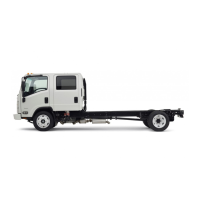
CLUTCHES AND TRANSMISSIONS 7-16
COMPONENT PART REPLACEMENT
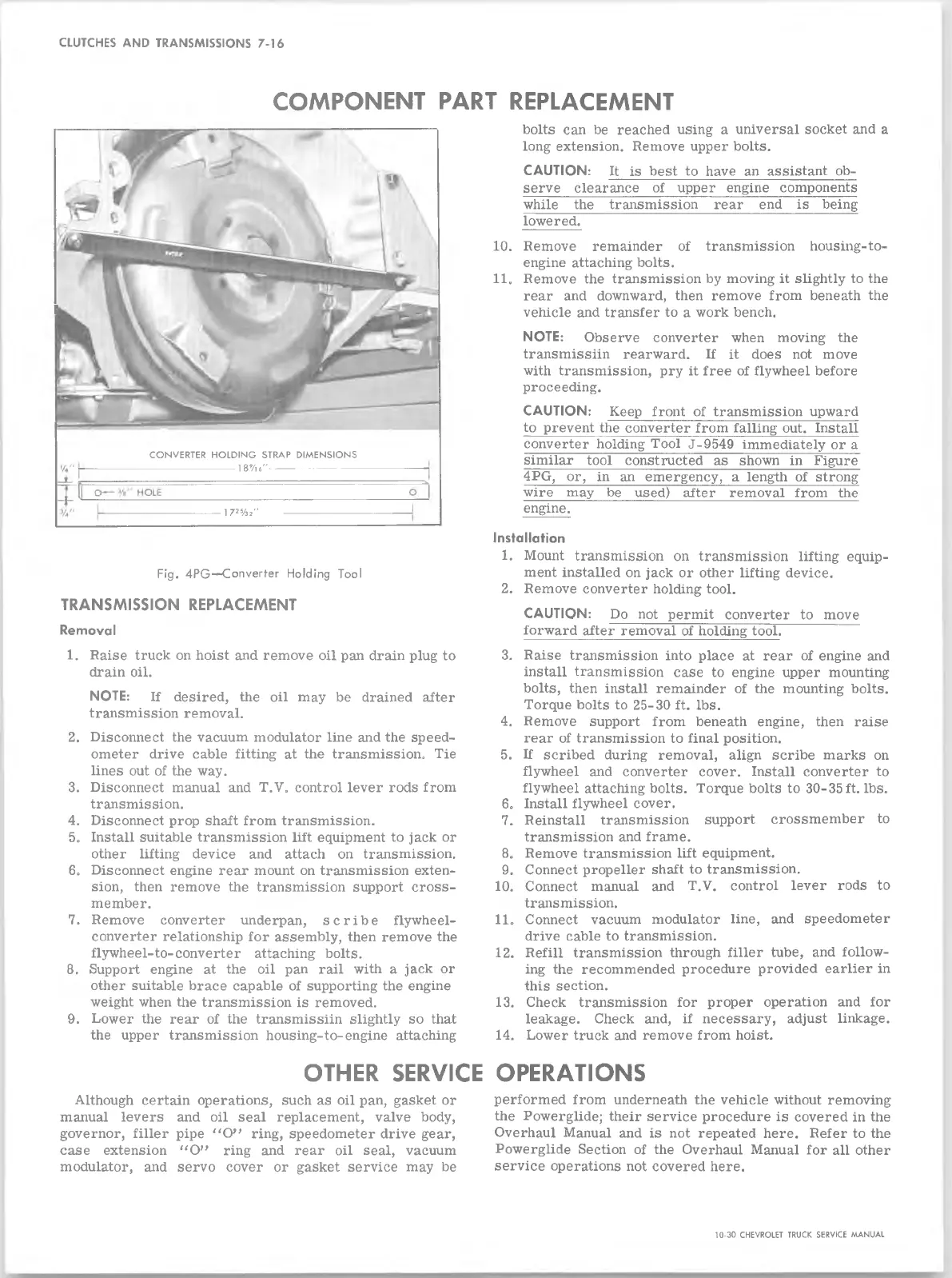
Fig. 4PG—Converter Holding Tool
TRANSMISSION REPLACEMENT
Removal
1. Raise truck on hoist and remove oil pan drain plug to
drain oil.
NOTE: If desired, the oil may be drained after
transmission removal.
2. Disconnect the vacuum modulator line and the speed
ometer drive cable fitting at the transmission. Tie
lines out of the way.
3. Disconnect manual and T.V0 control lever rods from
transmission.
4. Disconnect prop shaft from transmission.
5. Install suitable transmission lift equipment to jack or
other lifting device and attach on transmission.
6. Disconnect engine rear mount on transmission exten
sion, then remove the transmission support cross
member.
7. Remove converter underpan, scribe flywheel-
converter relationship for assembly, then remove the
flywheel-to-converter attaching bolts.
8. Support engine at the oil pan rail with a jack or
other suitable brace capable of supporting the engine
weight when the transmission is removed.
9. Lower the rear of the transmissiin slightly so that
the upper transmission housing-to-engine attaching
bolts can be reached using a universal socket and a
long extension. Remove upper bolts.
CAUTION: U_ is best to have an assistant ob
serve clearance of upper engine components
while the transmission rear end is being
lowered.
10. Remove remainder of transmission housing-to-
engine attaching bolts.
11. Remove the transmission by moving it slightly to the
rear and downward, then remove from beneath the
vehicle and transfer to a work bench.
NOTE: Observe converter when moving the
transmissiin rearward. If it does not move
with transmission, pry it free of flywheel before
proceeding.
CAUTION: Keep front of transmission upward
to prevent the converter from falling out. Install
converter holding Tool J-9549 immediately or a
similar tool constructed as shown in Figure
4PG, or, in an emergency, a length of strong
wire may be used) after removal from the
engine.
Installation
1. Mount transmission on transmission lifting equip
ment installed on jack or other lifting device.
2. Remove converter holding tool.
CAUTION: Do not permit converter to move
forward after removal of holding tool.
3. Raise transmission into place at rear of engine and
install transmission case to engine upper mounting
bolts, then install remainder of the mounting bolts.
Torque bolts to 25-30 ft. lbs.
4. Remove support from beneath engine, then raise
rear of transmission to final position.
5. If scribed during removal, align scribe marks on
flywheel and converter cover. Install converter to
flywheel attaching bolts. Torque bolts to 30-35 ft. lbs.
6. Install flywheel cover.
7. Reinstall transmission support crossmember to
transmission and frame.
8. Remove transmission lift equipment.
9. Connect propeller shaft to transmission.
10. Connect manual and T.V. control lever rods to
transmission.
11. Connect vacuum modulator line, and speedometer
drive cable to transmission.
12. Refill transmission through filler tube, and follow
ing the recommended procedure provided earlier in
this section.
13. Check transmission for proper operation and for
leakage. Check and, if necessary, adjust linkage.
14. Lower truck and remove from hoist.
OTHER SERVICE OPERATIONS
Although certain operations, such as oil pan, gasket or
manual levers and oil seal replacement, valve body,
governor, filler pipe “O” ring, speedometer drive gear,
case extension “O” ring and rear oil seal, vacuum
modulator, and servo cover or gasket service may be
performed from underneath the vehicle without removing
the Powerglide; their service procedure is covered in the
Overhaul Manual and is not repeated here. Refer to the
Powerglide Section of the Overhaul Manual for all other
service operations not covered here.
CONVERTER HOLDING STRAP DIMENSION S
---------------------------------- 1 8 9/ l6 "-----------------------------------
17 2% 2"
10-30 CHEVROLET TRUCK SERVICE MANUAL
 Loading...