11/2008 Chicago Pneumatic Compressors
Page 2 62 305 549 65
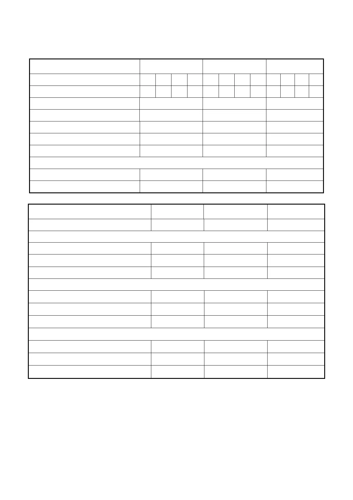
TECHNICAL DATA
STANDARD MACHINES
CPC MODEL 40 50 60
Nominal pressure at full flow
PSI 100 125 150 175 100 125 150 175 100 125 150 175
Actual flow *
(as per ISO 1217 : 1996)
cfm 166 152 137 118 208 185 164 150 268 234 209 196
Motor power hp 40 50 60
Ø Discharge orifice NPT 1.25” 1.25” 1.5”
Sound level at 3.3 ft
(as per ISO 2157 + 3 db(A))
dB (A) 73 75 73
Capacity gal 5.02 5.02 6.08
Carryover ppm 3 3 3
* Suction pressure: 14.5 PSI abs - Relative humidity: 0 % - Ambient temperature: 68 °F
- Effective discharge pressure : 102 PSI, 138 PSI or 181 PSI (effective)
Dimensions
L x W x H
43.34 x 54.77 x 60.87 43.34 x 54.77 x 60.87 43.34 x 54.77 x 60.87
Approximate weight lbs 1532 1576 1742
CPC MODEL 40 50 60
Motor power hp 40 50 60
Main Voltage 230 Volt / 3 / 60Hz
Nominal current
(A)
123 152 190
Power supply cable
AWG 0 AWG 00 AWG 0000
Fuse protection (RK5) 150 175 200
Main Voltage 460 Volt / 3 / 60Hz
Nominal current
(A)
66 79 100
Power supply cable
AWG 0 AWG 00 AWG 0000
Fuse protection (RK5) 80 100 125
Main Voltage 575 Volt / 3 / 60Hz
Nominal current
(A)
46 57 71
Power supply cable
AWG 6 AWG 4 AWG 3
Fuse protection (RK5) 50 70 80
Connection of the electric plate to an external control box
• Install an RC filter on the KM1 coil.
• Install an RC filter on the KM2 coil.
• All connections between external parts and the compressor must be carried out using a shielded cable, which must be
grounded at one of its ends.
WARNING: the operation connection cables between the different elements must never follow the same path
as the existing power cords. A separate installation from the power cords must be carried out.
• Install an RC filter on all the relay coils of the external operation units.