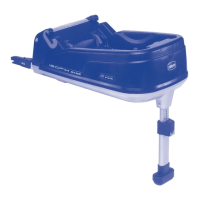
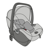
DESCRIPTION OF THE PARTS
A Isofix connectors
B Abdominal seat belt passage guide
C Compartment for storing the instruc-
tion booklet and 2 protective Isofix
connector caps
D Red/green indicator to signal that the
child car seat has, or has not, been
fitted correctly
E Support leg
F Isofix system adjuster lever
G Protective caps for Isofix connectors
H Release buttons
I Isofix system correct installation in-
dicator
L Support foot adjuster lever
M Red incorrect installation indicator
N Green support leg correct installation
indicator
INSTALLATION AND REMOVAL
FOR VEHICLES WITH THE ISO-
FIX SYSTEM
Installation
1. Remove the Isofix (A) connectors from
the base using the adjuster lever (F)
(Diag. 8).
Keep the lever up, and pull out the
ISOFIX system COMPLETELY (Diag. 8).
Ensure that the system has been pulled
out as far as possible.
2. Remove the Isofix connectors protec-
tion caps (G) using the release but-
tons (H) (Diag. 9a and 9b). Repeat
this procedure for both connectors.
Place the two caps in their compart-
ment (C)
WARNING! Store the caps carefully,
since they are indispensable for reinsert-
ing the ISOFIX system on the base when
the system is not in use.
3. Position the Isofix base on the rear
vehicle seat and fasten the Isofix con-
nectors to the anchorage points found
between the back rest and the car seat
(Diag. 10). You will hear a “click” when
the connectors fit into place.
WARNING! Check that the two in-
dicators (I) are green which means the
system has been installed correctly.
4. Push Isofix Base firmly against the
backrest of the car seat (Diag. 11) to
ensure maximum adherence.
5. Pull the base towards you a couple of
times to ensure the two connectors
are locked in place.
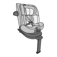
6. Position the support foot (E) and use
the adjuster lever to fix it in place (L)
(Fig. 12). Check the indicators (M and
N) on the foot to ensure it is fitted
correctly. When you can see the green
indicator (N), this means you have
installed it properly.
WARNING: Before attaching the child
car seat onto the base, check that the
stabiliser block is closed (Diag. 13).
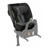
7. Attach the child car seat onto the base
(in a rear-facing position) and push it
downwards until you hear it click into
place (Diag. 14).
8. The indicator on the side (D) will turn
green (Diag. 15) when the child car
seat is securely and correctly locked
in place.
9. Check that the child car seat is cor-
rectly fitted to the base by trying to
lift the front and rear sections.
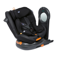
10. When it has clicked into position,
turn the child car seat handle bar as
far as possible (A) against the vehicle
seat backrest (Diag. 15).
To remove the child car seat