22
child’s body.
rWARNING: If you purchase a mat-
tress to add to the internal lining
separately, make sure it is suitable
for the product. Dimensions: L. 780
mm, W. 300 mm, H. 20mm. Do not
add another mattress on the upper
pa
rt of the mattress of the size rec-
ommended by the manufacturer.
r#FGPSFBTTFNCMZDIFDLUIBUOFJUIFS
the product nor any of its compo-
nents have been damaged during
transportation. In this case, do not
use and keep out of reach of chil-
dren.
r%P OPU MFBWF BOZUIJOH JOTJEF UIF
carrycot that might reduce its
depth.
r,FFQ UIF QMBTUJD CBHT BXBZ GSPN
children to prevent choking haz-
ards.
r1SPEVDUT MFGU JO UIF TVO XJMM PWFS-
heat; leave them cool down before
placing your child.
rWARNING: Never leave your child
unattended.
rWARNING: Never use this product
on a stand.
r5IF DBSSZDPU JT OPU EFTJHOFE GPS
children to sleep in for a long pe-
riod of time: this product is not a
substitute for a cot.
r8IFO GPMEFE TUPSF UIF DBSSZDPU
away from children.
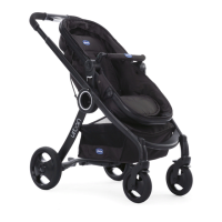
The Urban Plus seat can be used as a semi-rigid carrycot
with the supplied base. To transform the semi-rigid carry-
cot, follow the steps below.
28. Release the buckles under seat as described in step 23,
and position the seat horizontally (g. 28)
In semi-rigid conguration, remove the safety belts (see
paragraph REMOVE SAFETY BELTS), making sure to store
them away out of the reach of your child.
29. Open the base of the semi-rigid carrycot positioning it
horizontally until you hear the locking click (Fig. 29 – 29 A).
30. Position the base for the semi-rigid carrycot inside the
seat making sure to insert support “A” in the relevant slot
in the area of the child’s head on the structure (g. 30 –
30 A). Then complete the fastening by closing the support
“B” around the tube in
the area of the feet (Fig. 30B). After
attaching the rigid base at both ends, it must be xed to
the horizontal metal rod placed under the seat. The plastic
base, on the long sides, is equipped with two textile tapes
with press-stud (g. 30C). Take the end with the press-stud
and pass it through the textile hole placed on the side
of the seat (g. 30D-30E); then wrap the belt around the
horizontal metal rod (g. 30F) and pass the belt again into
the hole (30G) and complete the engaging by closing the
press-stud (30H). Repeat the same operation also on t
he
other side (30I). Now t the fabric lining fastening it to the
fabric of the stroller with the internal zip in the head area
and wrap the elastic part and fasten the buttons in the area
of the feet as described in steps 26-27.
WARNING: When the seat is in the semi-rigid carrycot con-
guration, it should be tted onto the stroller only in parent
facing position.
31. To complete the semi-rigid carrycot conguration, fas-
ten the bar to the structure inserting the ends into the rel-
evant slots.
WARNING: To make sure that the bar is fastened properly,
make sure that the green area in the upper part of the fas-
tening buttons is visible (Fig. 31). If it is not visible, the bar is
not fastened properly (Fig. 31A).
In semi-rigid carrycot conguration, when tted on the
stroller, we recommend positioning the bar facing your
child’s head, as shown in Figure 31 B.
32. The bar, if facing the child’s head, can be used as a carry-
ing handle for the semi-rigid carrycot.
WARNING: Before removing the semi-rigid carrycot from
the structure, make sure that the bar is fastened properly
by pulling it rmly upwards.
WARNING: Before removing the semi-rigid carrycot from
the structure with the child seated, make sure that the bar
is facing the child’s head.
To remove the carrycot from the frame, press the two but-
tons on the lateral joints (g. 32) and lift the semi-rigid car-
rycot holding the bar and pulling it up (g. 32 A).
33. Once the semi-rigid carrycot accommodating your
child is removed from the stroller frame, it can be placed on
a at surface (Fig. 33).
34. To return to the stroller or pram conguration, it is nec-
essary to remove the fabric lining and the semi-rigid car-
rycot base previously tted. To remove the base, release the
support “B” from the frame, opening it upward (Fig. 34), in-
cline the base and disengage it from the mechanism press-
ing the button of the support “A” (Fig. 34 A).
35. Once removed from the seat, the base can be folded on
itself to make it more compact acting on the two sliding
buttons in the lower part at the same time (Fig. 35).
WARNING: When not in use, keep the plate out of reach
of children.
PARKING BRAKE
The stroller is equipped with pedal parking brake located
on the rear axle.
36. To engage the parking brake, press the pedal down-
ward with one foot (g. 36).
37. To disengage the parking brake, push the pedal upwards
(Fig. 37)
WARNING: Always apply the brakes whenever the stroller
is stopped. Ne ver leave the stroller on a sloping surface with
 Loading...