2 CCH01726
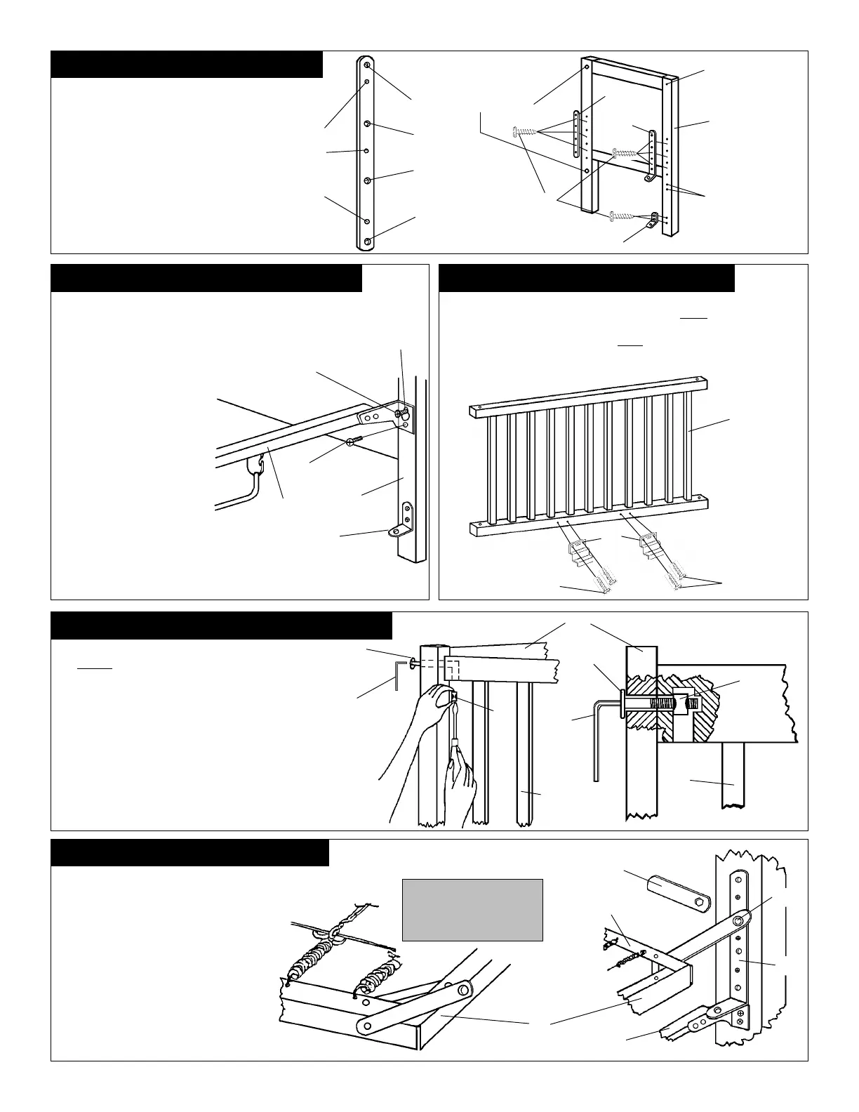
STEP 1 - DIAGRAM 1: INSTALL BRACKETS
Attach 4-Position Spring Brackets
D&S and Angle Brackets T to
both Headboard N and Footboard
O using Slotted/Phillips Wood
Screws
EE
EE
E, to be positioned ex-
actly as shown. NEVER RE-
MOVE 4-POSITION SPRING
BRACKETS
DD
DD
D &
SS
SS
S, ANGLE
BRACKETS
TT
TT
T, OR ANY OTHER
HARDWARE ITEM ATTACHED
WITH SLOTTED/PHILLIPS
WOOD SCREWS
EE
EE
E.
STEP 2 - DIAGRAM 2: ATTACH STABILIZER BAR
Attach Stabilizer Bar
JJ
JJ
J to
Headboard N & Footboard O
as shown. Also refer to DIA-
GRAM 6
.
Place a Slotted/Phillips
Machine Screw A into top re-
ceiving bushing
for installing
Stabilizer Bar
JJ
JJ
J
located in ends
NN
NN
N & O as shown, leave
screws extended - do not
tighten at this time. Place
the keyhole
(top hole in each
end of Stabilizer Bar
JJ
JJ
J
), over
top extended screws A as
shown.
Locate the bottom
Slotted/Phillips Machine
Screws
AA
AA
A into the lower re-
ceiving holes in each end of the
Stabilizer Bar
JJ
JJ
J and into re-
ceiving bushings located in
ends
NN
NN
N &
OO
OO
O. Tighten all four
Machine Screws
AA
AA
A securely
at this time.
STEP 3 - DIAGRAM 3: ATTACH GATE SHOES
Attach both Gate Shoes
CC
CC
C to lower rail
(inside)
of Dropside Q as shown
and affix with Slotted/Phillips Wood Screws
EE
EE
E.
Note: Gate Shoe Patent
No. will be visible when Gate Shoes
CC
CC
C are mounted. Tighten Slotted/
Phillips Wood Screws
EE
EE
E securely. Note: When disassembling crib in the
future, DO NOT REMOVE THE GATE SHOES OR ANY OTHER HARD-
WARE ITEM ATTACHED WITH SLOTTED/PHILLIPS WOOD SCREWS
EE
EE
E .
STEP 4 - DIAGRAM 4: ATTACH STATIONARY SIDE
Attach Stationary Side P to Headboard N & Footboard
O. NOTE:
Stationary Side
P
is one inch longer than
Dropside
Q
.
Insert each of the four Allenhead K-D
Bolts I into receiving holes located in corner posts of
crib ends
NN
NN
N & O as shown. Place Stationary Side
P in alignment and allow K-D Bolts
I I
I I
I to continue into
ends of top and bottom rails of Stationary Side P.
Insert each of the four K-D Bolt Plugs
LL
LL
L as shown.
Pull out each K-D Bolt
I I
I I
I just enough to allow the K-
D Bolt Plug
LL
LL
L to be fully inserted in hole. Tighten all four
K-D Bolts
II
II
I until secure using Allen Wrench
UU
UU
U
while
securing K-D Bolt Plugs
LL
LL
L with a Standard Slotted
Screwdriver. CAUTION: DO NOT OVERTIGHTEN.
STEP 5 - DIAGRAM 5: INSTALL SPRING
Locate "Tabs" on Crib Spring
RR
RR
R and rotate
Tabs upward. Position the (4) Tabs at-
tached to ends of Crib Spring
RR
RR
R to mount to
selected position in the 4-Position Spring
Brackets D and
SS
SS
S mounted on ends
NN
NN
N and
OO
OO
O. Install a Hexhead Machine Screw B
through the (4) Crib Spring Tabs and into a
receiving hole in each 4-Position Spring
Bracket
DD
DD
D &
S S
S S
S then tighten securely with
enclosed Hex Wrench F. Follow the same
procedure when changing spring height at
a later date. Check Hexhead Machine Screws
BB
BB
B periodically and tighten if needed.
A Extended
Connected View
Holes to
Receive
Slotted/
Phillips
Wood
Screws
E
S
4-Position
Holes
Receive
Hexhead
Machine
Screw B
to be placed
in selected
position hole
for Crib
Spring
R
positioning
CLOSE UP VIEW
Threaded inserts for
installing J.
Threaded inserts for
installing K.
Thru holes for
installing P.
E
D
S
T
O
T
O
A
J
Keyhole
E
C
Q
E
O
I
I
U
L
P
U
L
P
Tab
To Relocate Crib Spring
R, Remove Hexhead
Machine Screw B with
Hex Wrench F.
Tab
R
F
B
S
Top Surface
J
 Loading...