02
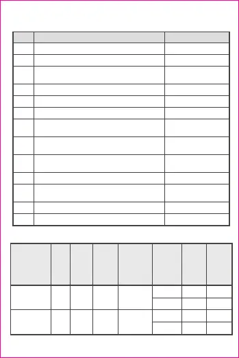
Table 3 Main Circuit Technical Parameters 2
Content
Rated operating voltage Ue(V)
Rated frequency (Hz)
Rated duty system, specify level of intermittent
duty (if any)
Rated insulation voltage Ui(V)
Rated impulse withstand voltage Uimp(kV)
Enclosure protection class
Strip length of conductor (wire/busbar) before
being inserted into terminals (mm)
Cross-sectional area of conductor
(wire/busbar) (mm )
2
Maximum allowable number of conductors
(wire/busbar)
Size of terminal fastening screw (or bolt)
Tightening torque of terminal fastening screw
(N.m)
Operation frequency (time/hour)
Available contactor
690V and below
50/60
Continuous duty system
690
8
IP20
10
4~25
1
M8
6
≤25
NC1, NC8
No. Parameters
1
2
3
4
5
6
7
8
9
10
11
12
13
Table 4 Basic Parameters of Auxiliary Contacts
Instantaneous
auxiliary contact
assembly
Instantaneous
auxiliary contact
assembly
Name
Model
Terminal
mark
Rated
insulation
voltage
Ui
V
Conventional
free air
thermal
current Ith
A
Application
category
Rated
operating
voltage
Ue
V
Rated
operating
current
Ie
A
NS2-AE20
NS2-AE11
13-14,
23-24
13-14,
21-22
250
250
2.5
2.5
AC-15
AC-15
DC-13
DC-13
230/240
230/240
60
60
0.5
0.5
0.15
0.15