Model 108 Two Motor Tandem Installation Instruction
11
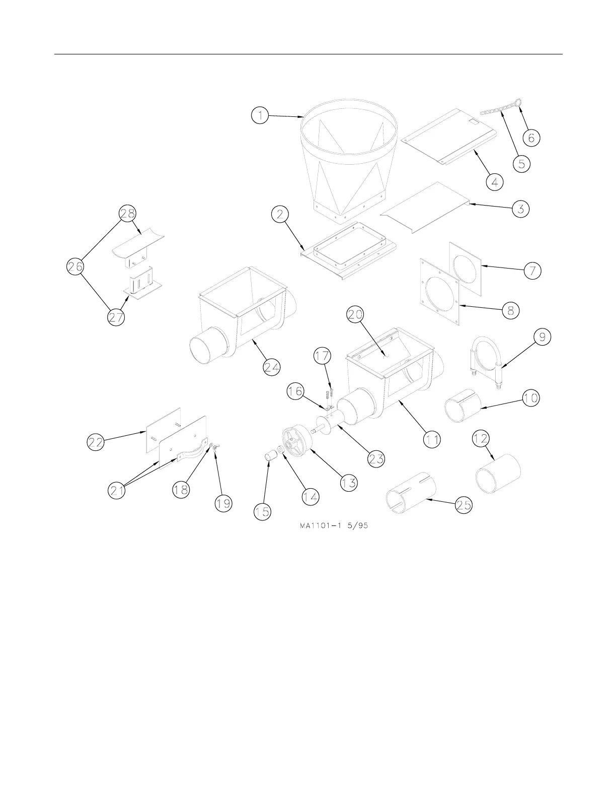
Two Motor Tandem Boot Parts Listing
Key Description Part No.
1 Straight-Out Upper Boot 6093
2 Transfer Plate 4359
3 Slide 4357
4 Slide Shield 4876
5 Chain 2128-1
6 Ring 1706
7 Neoprene Seal 34334
8 Seal Ring 8117
9 Tube Clamp (for STEEL systems) 34338
Tube Clamp (for PVC systems) 14373
10 Tube Insert 34337
11 Boot Body Weldment 30386
12 Tube Connector (for PVC syst.) 34557
13 Bearing Cap Assembly 30314
14 5/8” Set Collar 1386
15 Safety Cap 29703
16 Anchor Clamp 7703
17 5/16-18x7/8” Sock. Hd. C.S. 6850-1
18 Sealing Washer 8491
19 5/16-18 Wingnut 2146
Key Description Part No.
20 Baffle 14239
21 Cover Weldment 6301
22 Back Plate Assembly 6298
23 Anchor Weldment 34369
24 Straight-Thru Boot Body Weld. 30385
25 Model 108 Connector (steel sys) 30277
26 Boot Support Assembly 9987
27 Support Weldment 13044
28 Shoe Weldment 13047
-- Transfer Plate Assembly 7856
Note: Items #2 through #24 make up the Lower Boot
Assembly (part no. 34341).
Items #2 through #6 make up the Slide and Transfer Kit
(part no. 6284).
The Model 108 Connector (item #25) may be ordered with
(2) Tube Clamps (part no. 34338) as a kit under part no.
34419.
 Loading...

