Document # 49044IM1
Revision 7.5 18
Dated February 16, 2017
Calibration
NOTE: Calibrate ALL test channels, even if only one channel is
out of tolerance. This will ensure that all LEDs are set to the
same intensity.
1. Click on Aggregometer, select Reset Channel and then select
ALL Channels. Click on OK.
2. After wiping the outside with a Kim Wipe®, place BLACK
cuvette in PRP well of Channel 1 and place PPP water
cuvette in PPP well.
3. Click on the “Activate” bar for Channels 1 through 8.
4. Press the Baseline button for Channel 1 and hold until the
tracing reaches a full 100% of graph before releasing.
Tracing will then return to 0% of graph.
5. Transfer the BLACK cuvette in PRP well and water cuvette in
PPP well to Channel 2 and repeat Step 4.
6. Repeat Step 5 for Channels 3 through 8.
7. Remove Black cuvette from test well.
8. Click on the “Start” Bar for Channels 1 through 4.
9. After wiping the outside with a Kim Wipe® and keeping the
Alignment Marks left center, place the PRP water cuvette in
Channel 1 PRP well and the “P” water cuvette in Channel 1
PPP well.
10. Place the key in the calibrate switch on the module
containing Channels 1 through 4 and turn the key clockwise
90°and keep it in this position. Since calibration does not
start until the baseline is set, all four (4) channels can be
calibrated.
11. Set the timer for one minute but do not start. Press the Set
Baseline button for Channel 1, hold for a second, then
release. Start the timer as it may take up to a minute for the
channel to calibrate. During this minute DO NOT touch or
move the samples. Moving the samples may cause
inaccuracies in the calibration. Wait for the one minute [or
when tracing runs stable for around 20 seconds] before
proceeding to the next step.
NOTE: Disregard traces during calibration.
12. After waiting one minute, or when tracing stabilizes in
Channel 1 … Repeat steps 9 through 11 for Channel 2, then
3, then 4. Calibration key remains ON throughout this
process.
13. Once step 12 is completed for all four (4) channels, turn OFF
the calibration mode by turning calibrate key counter-
clockwise 90° and remove the key from the lock.
Calibration of Module 1 is now completed.
14. To calibrate Channels 5, 6, 7 and 8 in Module 2, beginning
with Channel 5, repeat steps 8 through 13above, using the
calibrate key in that module.
15. If required, SAVE and PRINT the test.
Post Calibration test
[Confirm the Calibration Key has been removed from
lock]
1. Under the AGGREGOMETER window, select or set-up a Test
Procedure page for Optical mode. Click on OK.
2. Select RUN NEW PATIENT under AGGREGOMETER and Click
on OK.
3. After wiping the outside with a Kim Wipe®, place BLACK
cuvette in Channel 1 PRP well and the PPP water cuvette in
the PPP well of Channel 1, with the alignment mark placed
left center.
4. Click on the Channel 1 “Activate” bar. [NOTE: If this test is to
be SAVED, Click on the “Start” Bar for Channel 1. If not
saving, the following steps can be performed after clicking
on the “Activate” button.]
5. Push and Hold the Set Baseline button until the tracing
reaches a full 100% of graph before releasing. Tracing will
then return to 0% of graph.
6. After wiping the outside with a Kim Wipe®, replace the
BLACK cuvette in the PRP well with the PRP water cuvette
with the alignment mark placed left center. The tracing
should move near 100% on the graph. Allow to run for a
few seconds and note the position where the tracing
stabilizes. (Ex: 97%)
7. Repeat Steps 3 through 6 for Channel 2, then repeat for
Channels 3, 4, 5, 6, 7 and 8. Be sure to use the PPP water
cuvette in the PPP wells and the PRP water cuvette in the
PRP wells. Also be sure to place the Alignment Mark to the
left center of each test well and to wipe the outside of the
cuvettes with a Kim Wipe® when placing into the test well.
8. If any tracing is > 4% from 0% or 100% on the graph,
calibration of that Channel will need to be repeated,
following the previous calibration steps.
9. If saving the test … Once all channels are completed, Click on
the STOP icon followed by the SAVE icon and the PRINT icon
to save and print this test.
NOTE: If the tracings are > 4% from 0% or 100% on the graph,
this may indicate that Auto-Calibration was not set properly.
Recheck the two water cuvettes to be sure they match. See
Appendix A for further instructions on matching water cuvettes,
then repeat the entire calibration procedure. Be sure to wipe the
cuvettes with a KimWipe
®
each time they are placed into a test
or reference well. If, after the second attempt, the results are
> 4%, the system may need Service. Contact Chrono-log Service
Department at 1-800-247-6665 for further assistance.
Additional Post Calibration test for Instruments
with PPP Select Switches - This section provides for the
ability to check each channel’s calibration against the Channel 1
PPP Reference.
[Confirm the Calibration Key has been removed from
lock]
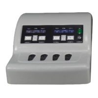
SELECT Pushbutton(s) – allows for toggling between the Stirring
Speed, Temperature and PPP/Reference Settings.
SET Pushbutton(s) - sets the Stirring Speed, Temperature and
PPP/Reference, depending on which feature is selected. Each
time the SET button is pushed, the selected function is
incremented until it reaches the maximum setting.
NOTE: One SELECT and SET pushbutton controls two channels in
tandem. For example, Channels 1 & 2, Channels 3 &4, Channels 5
& 6 and Channels 7 & 8 are set in pairs.
1. Set all Channels to Reference Channel 1 PPP
a. Push SELECT pushbutton for Channels 1 and 2 until
PPP/Reference setting is displayed on the LCD screen.
b. Push SET pushbutton for Channels 1 and 2 until the
reference to Channel 1 PPP is displayed.
 Loading...