•
BRAKES
5
-
1
BRAKES
DIESEL
VACUUM
PUMP
INSTALLING
VACUUM-STEERING
PUMP
ASSEMBLY
LOW
VACUUM
WARNING
SWITCH
PUMP
ADAPTER
REPLACEMENT
REMOVING
VACUUM-STEERING
PUMP
ASSEMBLY
CONTENTS
page
1
5
1
4
VACUUM
PUMP
DIAGNOSIS
...
VACUUM
PUMP
OPERATION
..
VACUUM
PUMP
REPLACEMENT
VACUUM
PUMP
SERVICEABILITY
page
..
2
..
1
..
4
..
1
DIESEL
VACUUM
PUMP
A
new design power brake vacuum pump
is
used
on
1991-1/2 AD models
with
the Cummins turbo die-
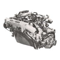
sel engine. However, the new vacuum pump
is
still
combined
with
the power steering pump into
a
single
assembly (Fig. 1).
The new vacuum pump is
a
constant displacement,
vane-type pump. Vacuum is generated by four
vanes
mounted in the pump rotor. The rotor
is
located in
the pump housing
and is
pressed
onto
the
pump
shaft.
The vacuum and steering pumps are both operated
by
a
single drive
gear
pressed
onto the vacuum pump
shaft. The drive
gear
is
operated by
.
the camshaft
gear.
The vacuum and power steering pump shafts
are
connected by
a
coupling. Each pump shaft
has an
adapter
with
drive lugs that
engage
in the coupling.
The vacuum pump rotating components are
lubri-
cated by engine
oil.
Lubricating
oil is supplied to the
pump through
an
oil
line
at' the underside of the
pump housing.
VACUUM
PUMP
SERVICEABILITY
The vacuum pump is not
a
serviceable component.
If
diagnosis indicates
a
pump malfunction, the pump
must
be
removed and replaced
as an
assembly. Do
not
disassemble
or attempt to repair the pump.
The combined vacuum and steering pump assembly
must be removed for
access
to either pump. However,
the vacuum pump can be removed
without
having to
disassemble
the power steering pump.
If
the power steering pump requires service, simply
remove
the
assembly and
separate
the two pumps.
Refer
to the
pump removal and installation proce-
dures
in this section.
LOW
VACUUM
WARNING
SWITCH
A
vacuum switch
is
used to monitor output of the
vacuum pump.
The
switch
is in
circuit
with
the
brake warning
light.
VACUUM
GEAR
ADAPTER
J9105-94
Fig.
1
Vacuum
And
Steering
Pump
Assembly
A
vacuum
hose
connects the switch
to
the power
brake booster. A
wire
harness
connects the switch to
the brake warning
light.
The switch
is
mounted
on the
driver side inner
fender panel just below the hood hinge (Fig. 2).
VACUUM
PUMP
OPERATION
Vacuum
pump output
is
transmitted to the power
brake booster through a supply
hose.
The
hose
is con-
nected to an outlet port on the pump housing and to
the check valve in the power brake booster.
Pump output
ranges
from
a
minimum
of 8.5 to
25
inches vacuum.
The pump rotor and
vanes
are rotated by the pump
drive
gear.
The drive
gear
is
operated by the cam-
shaft
gear.
Booster vacuum
level
is
monitored by
a
warning
switch
(Fig.
2).
The switch consists
of a
vacuum
chamber that
measures
vacuum
level
and
a
sensor
in
circuit
with
the brake warning
light.
 Loading...