Do you have a question about the Chrysler 1991 and is the answer not in the manual?
Covers general information about the engine.
Details the A/C system.
Information regarding the brake system.
Covers the cooling system specifications and procedures.
Information on emission control systems.
Covers exhaust and intake manifold service.
Details the fuel system components and diagnostics.
Information on the steering system.
Covers the speed control system operation and testing.
Information on the transmission system.
Electrical wiring diagrams for various systems.
Details the diesel vacuum pump used in the system.
Explains how the vacuum pump operates.
Procedures for diagnosing vacuum pump issues.
Steps to remove the vacuum-steering pump assembly.
Procedures for installing the vacuum-steering pump assembly.
Overview of changes to the diesel cooling system.
Steps for removing the radiator.
Procedures for installing the radiator.
Cooling system capacities and specifications.
Removal and installation of the overdrive lockout switch.
Explains the speed control system's operation and components.
Safety warning regarding speed control usage.
Procedures for testing the speed control system.
Index of wiring diagrams by component name and sheet number.
Wiring diagrams for A/C and heater components.
Wiring diagrams for the anti-lock brake system.
Wiring diagrams for the vehicle's charging system.
Wiring diagrams for front lighting systems.
Wiring diagrams for the fuel tank system.
Wiring for interior lighting controlled by headlamp switch.
Wiring diagrams for the speed control system.
Wiring diagrams for the starter system.
Wiring for stop, turn, and hazard flasher systems.
Wiring diagrams for the windshield wiper system.
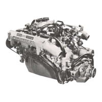
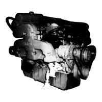
Overview of the 5.9L Cummins Turbocharged/Intercooled diesel engine.
Provides detailed specifications for the 5.9L diesel engine, including bore, stroke, and torque.
Procedures for diagnosing engine malfunctions.
Lists performance-related causes and corrections for engine issues.
Steps for servicing engine components.
Detailed engine specifications including valve train, cylinder head, and crankshaft dimensions.
Lists torque specifications for various engine components.
Covers removal and installation of the exhaust manifold.
Service for intake manifold cover and air intake heater.
Procedures for turbocharger removal and installation.
Information on the diesel fuel injection system.
Overview of the engine controller's diagnostic capabilities.
Details about the Single Board Engine Controller (SBEC).
How battery voltage affects the engine controller.
Brake switch input to the engine controller.
Charge air temp sensor input to the controller.
Crank signal input to the engine controller.
Ignition switch run position input to the controller.
Overdrive control inputs to the engine controller.
Coolant temp switch function and effect on transmission.
Transmission fluid temp switch function.
Park/neutral switch input for transmission and speed control.
TPS input to engine controller for shifting and speed control.
Speed sensor input for shifting, speed control, and operation.
WIF sensor input to controller for warning lamp.
How the controller operates air intake heater relays.
Operation of air intake heaters for startup and warmup.
Engine controller powers up and energizes heaters based on temp.
Post-heat cycle operation based on intake air temp.
How the wait-to-start lamp operates.
How the water-in-fuel lamp operates.
KSB solenoid function, location, and circuit.
Ignition switch ON sequence of operations.
Events occurring when ignition is turned to start.
Engine controller actions during warm-up.
Engine controller monitoring and transmission control during cruise/idle.
How speed control and sensors affect acceleration and overdrive.
How speed control and sensors affect deceleration and overdrive.
Diagnostic procedures for the diesel fuel system.
Importance of visual checks for fuel injection system.
Testing the throttle position sensor using a voltmeter or DRB II.
Troubleshooting guide for diesel fuel injection system issues.
Importance of checking injection pump timing.
Procedures for setting injection pump timing.
Overview of the power steering system.
Details the power steering pump's characteristics.
Information on pump removal and installation.
Steps for removing the power steering pump assembly.
Procedures for installing the power steering pump assembly.
Overview of the heavy-duty A518 automatic transmission.
Differences in the diesel A518 transmission case.
Details about the torque converter used for diesel applications.
New overrunning clutch design in diesel A518.
Heavy-duty planetary gear carriers in the diesel A518.
Clutch pack configurations for the diesel A518.
Diesel A518 governor weight assembly details.
How temperature switches control fourth gear operation.
Changes in service methods for the overrunning clutch.
Service procedures for the new overrunning clutch.
Steps to remove clutch components from the transmission.
Procedures for installing clutch components.
Detailed procedures for overhauling the SD-709 compressor.
Steps to isolate the compressor from the system.
Procedure for purging air from the compressor.
Covers compressor removal and installation.
Details the magnetic clutch operation and components.
Steps for removing the magnetic clutch.
Procedures for removing and installing the compressor shaft seal.
Covers removal and installation of the cylinder head and valve plate.
Lists torque specifications for A/C compressor components.
Information on exhaust emission controls.
Components of the diesel engine air inlet system.
Operation of air intake heaters for engine warmup.
How the engine controller operates air intake heater relays.