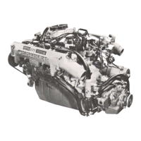
11
- 4
EXHAUST
SYSTEM
AID
INTAKE
MANIFOLD
Fig.
10 Oil
Supply
Line
and
Intercooler Inlet Duct
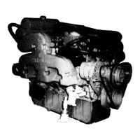
(3)
Remove the compressor housing
V-Band
clamps
(Fig.
11).
(4)
Remove the compressor housing and inspect for
impeller
contact
(Fig.
11).
(5)
Remove the
square
cut
O-ring
(Fig.
11).
(6)
Remove the
impeller
nut
(Fig.
11).
Turn
the
im-
peller
nut to the
right
to loosen. The nut and shaft
have
left
hand threads.
Fig.
11
Compressor
Homing
and
Impeller
(7)
Remove the
impeller
and inspect the blades for
damage. The wheel and shaft assembly is balanced
as a
unit.
If
the
impeller
is damaged the complete as-
sembly
must be replaced.
(8)
Remove the diffuser bolts and lockplate (Fig.
12).
~
(9)
Remove the diffuser and discard the
O-ring
(Fig.
13).
Fig.
12
Diffuser
and
Lockplate
(10)
Remove the oil slinger and discard the piston
ring
(Fig.
13).
(11)
Inspect for cracks and excessive wear.
O-RING
OIL
Fig.
13
Diffuser,
Q-Ring
and Oil
Slinger
(12)
Remove the oil
baffle
(Fig.
14).
(13)
Remove the thrust bearing and retainer screws
(Fig.
14). Do not
reuse
the thrust bearing.
(14)
Remove the thrust
collar
(Fig.
14).
(15)
Inspect the
collar
for excessive wear.
(16)
Remove the turbine housing
lock
plates and
clamp
plates
(Fig.
15).
(17)
Remove the bearing housing
(Fig.
15).
(18)
Remove the turbine shaft and
heat
shield (Fig.
16).
(19)
Inspect the turbine blades and the shaft for ex-
cessive wear.
(20)
Remove and discard the piston
ring
type seal
(Fig.
16).
 Loading...