Do you have a question about the CIAC CK43BV028-CYJ1H and is the answer not in the manual?
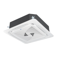
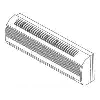
Lists various indoor unit types like Cassette, Duct, Slim Duct, etc.
Details key features like DC Inverter Compressor, DC Inverter Motor, Precise Control, 180° Vector Control.
Detailed specs for power supply, cooling, heating, compressor, outdoor fan motor, etc.
Diagram illustrating the refrigerant flow and components for a specific model.
Shows external dimensions and fixing hole details for the outdoor unit.
Illustrates the electrical connections and components for the control board.
Explains how to calculate cooling capacity using various compensation values.
Shows continuous operation limits for cooling and heating based on indoor/outdoor temperatures.
Presents sound pressure levels across different frequency bands for various models.
Crucial safety warnings and precautions for installing the outdoor unit.
Step-by-step instructions for installation, including checks and place selection.
Detailed steps for performing a leakage test using nitrogen.
Instructions for evacuating the system using a vacuum pump.
Method for opening and closing stop valves.
Diagrams and explanations for communication wiring between units.
Describes how units operate in cooling and heating modes, including simultaneous control.
Explains the function of each DIP switch on BM1 for various settings like fan selection and defrost.
Describes the meaning of various codes and parameters shown on the digital tube display.
Details the control logic for compressor startup, including speed and timing.
Lists failure codes, their definitions, descriptions, and remarks for the outdoor unit.
Flowchart for diagnosing and resolving temperature sensor issues.
Flowchart for diagnosing communication problems between indoor and outdoor units.
Flowchart for addressing outdoor EEPROM failure.
Flowchart for diagnosing 4-way valve reversing problems.
Flowchart for diagnosing high pressure switch shutoff issues.
Flowchart for handling discharge temperature too high protection.
Flowchart for addressing low oil temperature protection.
Flowcharts for low pressure and high compression ratio issues.
Flowchart for handling high pressure protection.
Flowchart for diagnosing low pressure switch failure.
Flowchart for low discharge temperature sensor protection.
Flowchart for diagnosing communication failures with the inverter module.
Flowchart for diagnosing current sensor failures.
Flowchart for addressing CT over current issues.
Flowchart for diagnosing DC motor blockages.
Flowchart for diagnosing lack of pressure drop between high and low pressure sides.
Flowchart for compressor current protection issues.
Flowchart for software-related transient over current in IPM module.
Flowchart for diagnosing current detection circuit abnormalities.
Flowchart for power module overcurrent issues.
Flowchart for handling overload protection.
Flowchart for compressor control issues.
Flowchart for high radiator temperature issues.
Flowchart for low DC bus voltage issues.
Flowchart for high DC bus voltage issues.
Flowchart for communication issues between transducer and control PCB.
Flowchart for software-related transducer over current.
Flowchart for diagnosing compressor startup failures.
Flowchart for transducer current detection circuit abnormalities.
Flowchart for abnormal radiator temperature sensor readings.
Flowchart for abnormal transducer power supply.
Flowchart for abnormal inverter board power supply.
Provides characteristic data for various temperature sensors used in the unit.
| Brand | CIAC |
|---|---|
| Model | CK43BV028-CYJ1H |
| Category | Air Conditioner |
| Language | English |