EasyManua.ls Logo

CIAT 99DA-SEI-EC01 User Manual

CIAT 99DA-SEI-EC01
6 pages
To Next Page IconTo Next Page
Page #1 background imageLoading...
Page #1 background image
Wiring diagram 99DA-SEI-EC01
Content Page
2-pipe units 2
2-pipe units change over 3
4-pipe units 4
2-pipe units with elecric heater 5
Connecting multiple fan coil units 6
Various settings are possible with this type of thermostat. Read the installation manual carefully before installation. For proper
operation, check the parameters indicated per system and adjust them if necessary.
To access the configuration menu, simultaneously press the and buttons for a few seconds until “COn
(configuration) appears on the display. Once entered in configuration menu, pressing scrolls through the
various parameters, identified with P and the parameter number, from P01 to P25.
When scrolling the parameters pressing button or or displays its current value.
To change the value, when it is displayed, press button or .
The configuration end is displayed with “End”. Press again to save the configuration and return to normal operation.
The extended parameters C01-C23 allow an advanced thermostat configuration. When the display shows COn“ at
configuration start or “End“ at configuration end, press the button to access the extended parameters.
APPLICATION
Thermostat type: 99DA-SEI-EC01
Fan coil units with EC fan (HEE): 0-10V control
Actuators of the 2- or 3-way valves: 230V on/off
REMARKS
1: All electrical connections must be made in accordance with the local regulations
2: ---------- External cables (not supplied by CIAT)
3: Minimum cable diameter 1,5 mm
2
(230V~)
4: Use shielded cable for 0-10V signal cable of the fan motor
5: For other connections/information, see the electrical wiring diagram of the relevant unit
18-05-2022
Question and Answer IconNeed help?

Do you have a question about the CIAT 99DA-SEI-EC01 and is the answer not in the manual?

CIAT 99DA-SEI-EC01 Specifications

General IconGeneral
BrandCIAT
Model99DA-SEI-EC01
CategoryThermostat
LanguageEnglish

Summary

Thermostat Configuration and Operation

Accessing Configuration Menu

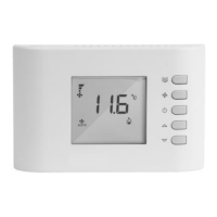
Simultaneous press of ' ' and ' ' buttons to access configuration menu.

Navigating Parameters

Scrolling through parameters P01-P25 using ' ' and ' ' buttons.

Changing Parameter Values

Pressing ' ' or ' ' buttons to change displayed parameter values.

Saving Configuration

Pressing ' ' button again to save configuration and return to normal operation.

Extended Parameters Access

Accessing advanced thermostat configuration (C01-C23) via '+' button.

2-PIPE FAN COIL UNITS Wiring Diagram

System and Fan Speed Parameters

Configuration parameters P01 (system type) and C15/C16 (fan speed).

Mode Selection

Selecting heating/cooling modes by holding ' ' button.

Parameter C02 Explanation

C02: 30 (if water temp. higher than this value → heat).

Terminal Explanations

Explanation of terminals like E/I, RDC, SM, SA, CF, and XB, TB, A1F/X2.

2-PIPE FAN COIL UNITS with Water Sensor

Water Sensor Integration

Installing water temperature sensor (SM) on pipe for change-over.

Temperature-Based Change-over

Parameters C01 (cool) and C02 (heat) for water temperature control.

Fan Speed Adjustment

Setting minimum (C15) and maximum (C16) fan speeds for ducting.

Explanation of E/I and RDC

E/I as N/A, RDC for 'Economy' function (set P18).

4-PIPE FAN COIL UNITS Wiring Diagram

System Type and Fan Speed Settings

Parameters P01 (system type) and C15/C16 (fan speed).

Automatic Change-over

Parameter P02: 0 or 1 for automatic heat/cool change-over.

Fan Speed Optimization

Maximum fan speed setting (C16) for ducting resistance.

Terminal Function Explanations

Explanation of RDC, SM, SA, CF terminals and unit terminals.

2-PIPE FAN COIL UNITS with Electric Heater

Electric Heater Fan Speed

Parameter C14 for minimum fan speed with electric heater activated.

System Type for Electric Heating

Parameter P01 set to 2 for system type with electric heater.

Fan Speed Settings

Parameters C15 (minimum) and C16 (maximum) fan speed.

Airflow and Fan Speed Notes

Notes on minimum airflow and maximum speed settings for ducting.

Connecting Multiple Fan Coil Units

Central Power Supply Requirement

Use one central power supply for multiple units, not separate ones.

Maximum Unit Connection

Connect up to 4 fan coil units to a single thermostat.

Electric Heating Connection

Connect electric heating units only if switched by a relay.

Inter-Unit Wiring

Wiring diagram for connecting multiple units to the thermostat.

Related product manuals