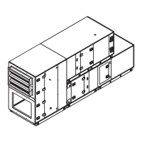
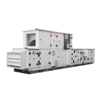
SINGLE FLOW AHU DUAL-FLOW AHU
1. Unwind the cables from the ends (the cables are prewound in the factory) 1. Unwind the cables from the ends (the cables are prewound in the factory)
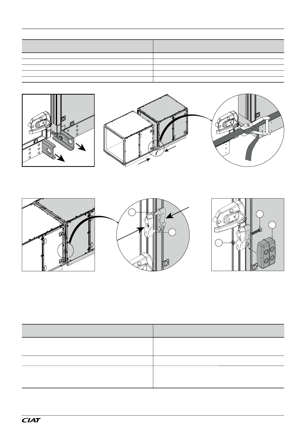
2. Route the cables into the lower frame and to the vertical raceway
3. Place the cables in the raceway
4. Feed the cables through the upper raceway 4. Feed the cables through the upper raceway
5. Route downwards into the unit 5. Route downwards into the unit
Ŷ 5HPRYHWKHOLIWLQJOXJVDQGXVHDVWUDSWREULQJWKHEORFNVWRJHWKHUWDNLQJFDUHQRWWRGDPDJHWKHIURQWSDQHOFRPSRQHQWV
:KHQEULQJLQJWKHEORFNVWRJHWKHUPDNHVXUHWKHYDULRXVFOHDWV¿WWRJHWKHUFRUUHFWO\
)LQDOLVH WKH DVVHPEO\ E\ VFUHZLQJ WKH FRQQHFWLQJ FOHDWV WRJHWKHU XVLQJ WKH PHWULF VFUHZ 0 QXW
VXSSOLHGLQWKHNLW
Ŷ &OLSWKHFRYHUVRQWRWKHFOHDWV
4
3
1
$VVHPEOLQJWKHPL[LQJRSWLRQLQVHOIFRQWDLQHGEORFNV
- )LWDJDVNHWRQWKHEHDULQJIDFHVRIWKHLQVXODWHGVOHHYHVOHHYHVXSSOLHGLQWKH$+8
- $ႈ[WKHVOHHYHWRWKHRXWVLGHRIWKH$+8DJDLQVWWKHPL[LQJGDPSHU[VKHHWPHWDOVFUHZ
- %ULQJWRJHWKHUWKHEORFNV
- &RQQHFWWKHVOHHYHWRWKH
nd
EORFNIURPWKHLQVLGHRIWKHXQLW
- $ႈ[WKHSDQHOWRSUHYHQWDFFHVVWRWKHVOHHYHFRQQHFWLRQ[VKHHWPHWDOVFUHZ
6.4 - OPTIONS: Adjustable feet, risers and risers + cylinders
Description Instructions
ADJUSTABLE FEET (cylinder with foot which is articulated and adjustable over
30 mm)
MIN. = HT 113 mm/MAX. = HT 145 mm
1. Remove the transport feet
2. Screw in the cylinders under the adjustable feet
3. Fit the adjustable feet with the M8 screws included in the transport feet positions
4. Use the cylinders to adjust the levelness
RISERS
HT200mm, HT300mm, HT400mm
1. Remove the transport feet
2. Fit the risers with the M8 screws included in the transport feet positions
RISERS + CYLINDERS (cylinder with foot which is articulated and adjustable over
30 mm)
MIN. = HT 260 mm/MAX. = HT 290 mm
MIN. = HT 360 mm/MAX. = HT 390 mm
MIN. = HT 460 mm/MAX. = HT 490 mm
1. Remove the transport feet
2. Screw in the cylinders under the risers
3. Fit the risers + cylinders with the M8 screws included in the transport feet
positions
4. Use the cylinders to adjust the levelness
6 - INSTALLATION
(1 &/,0$&,$7
®