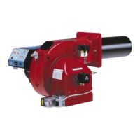
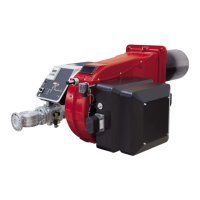
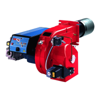
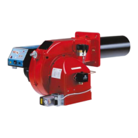
This document describes the UNIGAS RX92R-FGR, RX92-FGR, RX512R-FGR, RX512-FGR, RX515-FGR, RX520-FGR, and RX525-FGR series of gas burners, which are microprocessor-controlled using the Siemens LMV5x system. It also includes a service manual for the Siemens LMV5x control unit.
Function Description
The UNIGAS RX series burners are designed for gas operation, with the gas flowing from the supply line through a filter and governor, which regulates the pressure within specified limits. Actuators proportionally control the air damper and the gas butterfly valve to optimize gas flue values and achieve efficient combustion. An adjustable combustion head enhances burner performance by determining the flame's energetic quality and geometry. Fuel and combustion air are routed separately to the combustion chamber. The control panel on the burner's front side displays each operating stage.
The Siemens LMV5x control system, consisting of a central unit and a local programming unit (AZL), manages all burner control functions and provides an interface for user interaction. Key features of the LMV5x system include:
- No mechanical linkages, relying on electronic control.
- Built-in burner control box and gas proving system.
- Multiple flame checking devices for various applications.
- PID load controller for precise regulation.
- Control of up to six independent actuators for optimal burner setup.
- Best air/fuel ratio control with high repeatability and precision.
- Modbus communication for integration into building automation systems.
- Multilevel password protection for settings.
- PC-based settings adjustment.
- Adjustable prepurging, continuous ventilation, and post-purging times according to relevant standards.
- Settable proving system to activate on and off, with adjustable times for all valve volumes.
- Load controller settable to on and off.
- Thermal shock protection function for cold starts.
- Continuous operation and flame detection probe.
Important Technical Specifications
The RX series burners operate with natural gas (M) as the fuel type, with available versions supporting fully modulating (MD) operation. Blast tube options include standard (S) and extended (L). Gas connections vary in size from Rp2 (50) to DN100. The micro-processor control (EF) includes an electronic cam LMV5x and temperature-compensated flue gas recirculation (FGR), without O2 monitoring or inverter. Some models (EG, ER) may include an inverter and/or O2 monitoring.
Output and Gas Rate (Natural Gas):
- RX92R-FGR / RX92-FGR: Output min-max kW: 320-1870 / 680-2504 / 680-2800. Gas rate min-max (Stm³/h): 34-198 / 72-265 / 72-296.
- RX512R-FGR / RX512-FGR: Output min-max kW: 1280-3600. Gas rate min-max (Stm³/h): 135-381.
- RX515-FGR: Output min-max kW: 1065-4160. Gas rate min-max (Stm³/h): 113-440.
- RX520-FGR: Output min-max kW: 1600-4816. Gas rate min-max (Stm³/h): 169-510.
- RX525-FGR: Output min-max kW: 1550-6320. Gas rate min-max (Stm³/h): 164-669.
Electrical Specifications:
- Power supply: 230V 3~/400V 3N~ 50Hz (some models 400V 3N~ 50Hz).
- Total power consumption: 8 kW to 19 kW depending on model.
- Electric motor: 7.5 kW to 18.5 kW depending on model.
- Protection: IP40.
Environmental Conditions:
- Operating temperature: -10°C to +50°C.
- Storage temperature: -20°C to +60°C.
- Working service: Continuous.
- Suitable for indoor operation with a maximum relative humidity of 80%.
Gas Train and Control Components:
- Gas valves group (VGD and MBE) with built-in gas pressure governor and gas leakage pressure switch (PGCP).
- Pressure switches (PGMIN, PGMAX) and pressure transducer.
- Siemens VGD20/VGD40 gas valves with SKP2 pressure governor.
- MultiBloc MBE with VD-R pressure regulator and PS pressure sensor.
Usage Features
Installation:
- Installation must be performed by qualified personnel in compliance with regulations.
- Proper earthing is crucial for safety.
- Packaging materials should be disposed of safely.
- The burner must be firmly secured to the appliance.
- FGR pipe sizing is critical for FGR burners, considering flue gas temperature and air flow.
- Gas train components must be fitted correctly, ensuring proper sealing and flow direction.
- The double gas valve unit requires careful installation of flanges and O-rings.
- The burner must be correctly matched to the boiler, ensuring proper blast tube length and sealing with refractory material.
Operation:
- Before startup, ensure the control box is not in lockout, pressure switches/thermostats enable operation, and gas pressure is sufficient.
- For burners with gas proving systems, the test begins, and if leakage is detected, the burner locks out.
- The start-up cycle includes air damper to maximum opening, fan motor start, pre-purge, air damper to ignition position, ignition transformer energization, and gas valve energization.
- After ignition, the burner operates in low flame, then transitions to two-stage or fully modulating operation based on external thermostats or modulators.
- The AZL display shows operating phases and allows access to system parameters.
- Users can set temperature/pressure set-points and load percentages.
- Manual mode allows bypassing thermal protection or operating at fixed low flame.
- Cold start thermal shock protection (CSTP) can be enabled for slow boiler heating.
Adjustments:
- Air flow and fuel adjustments are performed at maximum output first, checking combustion parameters (CO2, O2) and combustion head pressure.
- Gas/air ratio curve points are set using the LMV system.
- Low flame output is adjusted to prevent condensation.
- Outlet pressure of the VD-R regulator is adjusted using the adjustment ring nut.
- Gas and air pressure switches are calibrated to ensure proper operation within specified pressure ranges.
- Combustion head position can be adjusted to optimize flame stability.
- Diffuser position and holes can be adjusted to improve flame stability and NOx/CO emissions.
Maintenance Features
- Routine maintenance should be carried out at least once a year, or every 6 months for continuous operation.
- All operations must be performed with the mains disconnected and fuel cutoff valves closed.
- Checks and Cleaning:
- Gas meter for leaks.
- Vent for cleanliness (clean with dry brush, non-corrosive detergents).
- All parts in contact with combustive air (air box, protection mesh, Archimedean screw) for obstructions (clean with compressed air or dry brush).
- Blast tube for cracks or anomalous holes (replace if necessary).
- Burner-boiler gasket (replace if necessary).
- Fan motor for anomalous noises and bearing condition (replace if necessary).
- Gas filter cartridge (clean or replace).
- Combustion head (remove and clean).
- Ignition electrodes (examine, clean, adjust, replace).
- Detection electrode/photoelement (examine, clean, replace if necessary, check detection circuit after startup).
- Levers and rotating parts (clean and grease).
- Burner room (clean every 2 months or more often).
- Room ventilation openings for obstructions.
- Gas Filter Maintenance:
- Close manual cutoff valve and bleed gas before opening.
- Remove cap, clean filtering cartridge with water and soap, blow with compressed air (or replace).
- Replace cartridge and O-ring correctly.
- Combustion Head Maintenance:
- Turn off burner and allow to cool.
- Remove cover, electrodes cables, and unscrew screws holding the gas manifold.
- Pull out the complete group, clean the combustion head with compressed air or scratchbrush.
- Replace O-ring correctly when reassembling.
- Electrode Adjustment and Replacement:
- Check ignition and detection electrodes after removing/adjusting the combustion head, ensuring no contact with metallic parts.
- Follow specific instructions and diagrams for electrode positioning based on type.
- To replace ignition electrodes: remove burner cover, loosen nuts, disconnect cables, loosen security dowels, shift group back, remove combustion head, loosen screw, remove and replace electrodes, then reassemble in reverse order.
- To replace detection electrode (natural gas burners): remove combustion head, loosen fixing screws with allen key, replace electrode, then replace combustion head.
- Check detection current with electrode using the provided scheme; replace electrode or detector if signal is low.
- Burner Service Term:
- Burner can last up to 20 years with optimal conditions and preventive maintenance.
- Technical diagnosis and potential repair/replacement are needed at the end of its service term.
- Seasonal Stop:
- Turn off main switch, disconnect power, close fuel valve.
- Disposal:
- Follow local regulations for material disposal.