77
77
7
GBGB
GBGB
GB
Scope of supplyScope of supply
Scope of supplyScope of supply
Scope of supply
Claropur BWClaropur BW
Claropur BWClaropur BW
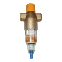
Claropur BW consisting of:
11
11
1 Top section in brass
22
22
2 Connection thread with reduction fittings
33
33
3 Transparent cylinder with filter element
44
44
4 Hose connection for flushing water supply
55
55
5 Turning knob for the backwashing element
ApplicationApplication
ApplicationApplication
Application
This filter is intended for the filtration of drinking
and service water. It protects the water pipes and
the connected water system parts from malfunc-
tions and corrosion damage due to impurities such
as rust particles, chippings, sand, hemp, etc.
The filter
cannotcannot
cannotcannot
cannot be used in applications with
chemically treated circulating water, process wa-
ter and cooling water for continuous cooling sys-
tems.
In applications with water containing coarse im-
purities, a coarse dirt separator must be used.
The filter is
not suitablenot suitable
not suitablenot suitable
not suitable for oils, greases, sol-
vents, soaps and other lubricating media nor for
the separation of water-soluble substances.
Attention:Attention:
Attention:Attention:
Attention:
In accordance with A In accordance with A
In accordance with A In accordance with A
In accordance with A
VB VB
VB VB
VB
WW
WW
W
asser asser
asser asser
asser
VV
VV
V
,,
,,
,
§ 12.2, the installation of the equipment may§ 12.2, the installation of the equipment may
§ 12.2, the installation of the equipment may§ 12.2, the installation of the equipment may
§ 12.2, the installation of the equipment may
only be carried out by the public water sup-only be carried out by the public water sup-
only be carried out by the public water sup-only be carried out by the public water sup-
only be carried out by the public water sup-
ply company or by an installation companyply company or by an installation company
ply company or by an installation companyply company or by an installation company
ply company or by an installation company
listed in the installer directory of a water sup-listed in the installer directory of a water sup-
listed in the installer directory of a water sup-listed in the installer directory of a water sup-
listed in the installer directory of a water sup-
ply companply compan
ply companply compan
ply compan
yy
yy
y
..
..
.
FunctionFunction
FunctionFunction
Function
The untreated water flows through the untreated
water inlet into the filter and from there from the
inside to the outside through the filter element into
the clean water outlet. Any impurities >90 µm are
trapped on the inside of the filter cloth. The filter
element needs to be cleaned by backwashing at
regular intervals.
For the backwashing process, the waste water
connection is opened by turning the turning knob
and the backwashing element is also turned. The
particles on the filter cloth are removed by suc-
tion and then washed out.
Installation conditionsInstallation conditions
Installation conditionsInstallation conditions
Installation conditions
Observe the local installation regulations, general
guidelines, general hygiene regulations and the
technical specifications.
A connection to the sewage system (discharge)
of min. DN 40 should be available.
Attention:Attention:
Attention:Attention:
Attention: The installation site must be protected
against frost and must ensure the protection of
the filter against e.g. solvent vapours, fuel oil, lees,
chemicals of any kind, UV radiation and heat
sources above 40 °C.
Attention: keep the plastic parts free fromAttention: keep the plastic parts free from
Attention: keep the plastic parts free fromAttention: keep the plastic parts free from
Attention: keep the plastic parts free from
grease, solvents and acidic as well as basicgrease, solvents and acidic as well as basic
grease, solvents and acidic as well as basicgrease, solvents and acidic as well as basic
grease, solvents and acidic as well as basic
detergentsdetergents
detergentsdetergents
detergents
..
..
.
The plastic parThe plastic par
The plastic parThe plastic par
The plastic par
ts mts m
ts mts m
ts m
ust be replacedust be replaced
ust be replacedust be replaced
ust be replaced
even if there is no visible damage after severeeven if there is no visible damage after severe
even if there is no visible damage after severeeven if there is no visible damage after severe
even if there is no visible damage after severe
concussions and shocks e.g. due to the useconcussions and shocks e.g. due to the use
concussions and shocks e.g. due to the useconcussions and shocks e.g. due to the use
concussions and shocks e.g. due to the use
of unsuitable tools or if dropped on stoneof unsuitable tools or if dropped on stone
of unsuitable tools or if dropped on stoneof unsuitable tools or if dropped on stone
of unsuitable tools or if dropped on stone
floors etc (danger of bursting). Avoid extremefloors etc (danger of bursting). Avoid extreme
floors etc (danger of bursting). Avoid extremefloors etc (danger of bursting). Avoid extreme
floors etc (danger of bursting). Avoid extreme
pressure impact.pressure impact.
pressure impact.pressure impact.
pressure impact.
InstallationInstallation
InstallationInstallation
Installation
Install filter according to its nominal width in cold
water pipes of the same dimensions and before
the equipment to be protected. Install stop valves
before and after the filter.
Assemble the connection fittings (
22
22
2) in the pipe
and install filter in flow direction (see flow direction
arrow) in the horizontal cold water pipe (see in-
stallation sketch).
Route the flushing water connection with hose to
the sewage channel or provide a collection basin
(capacity approx. 10 l).
Please note: According to DIN 1988, the flushing
water hose must be installed at a minimum dis-
tance of 20mm to the highest possible waste wa-
ter level (free discharge).
StartupStartup
StartupStartup
Startup
Check the filter and the flushing water pipe for
proper installation.
The stop valves must not be opened yet. Check
the transparent cylinder (
33
33
3) for proper fit and then
close the turning knob (
55
55
5) by turning it clockwise.
 Loading...