5
Y+ R-
POWER
VALVE
OUTRET
RS485
A B
TC1
Y+ R-
TC2
VLV B
DIN
GND
PS3
GND
PS2
GND
PS1
PWR
A B PWR GND
MODULE PORT
IN+
IN-
GND
R-
B-
A+
Y+
GND
Y+
R-
THERMO-
COUPLE
PORT
RS485
PORT
ALARM
OUTPUT
DOUT-
DOUT-
AUXIO
GND
DOUT+
GND
OPN-G
GND
CLS-R
OPN-G
GND
CLS-R
MAIN
VALVE
BATTERY-IN
GND
SOLAR
GND
PWR-OUT
BATTERY-OUT
PILOT
VALVE
POWER
PORT
DIGITAL
OUTPUTS
GND GND
GROUND
GND GND
DIGITAL
INPUTS
TRANS-
DUCER
PORT
TC2
TC1
MAIN
VLV A
PILOT
Permissive +
-
Proof of Closure +
-
PS2
PS1
ARControl BMS
Thermocouple 1 R-
Y+
Thermocouple 2 R-
Y+
Alarm -
+
Independent
Process Valve
+
-
Pilot Status +
-
+
-
+
Process 1 Valve
Process 2 Valve
+
-
+
Pilot Valve
Process 3 Valve
+
-
+
Transducer
Port
GND
B-
A+
Modbus
RS-485
PWR
+
-
GND
Maintenance &
Service
Contact Cimarron Energy, Inc.
for informaon in regard to
maintenance, parts, or service
at 1-844-746-1676 or visit
www.cimarronenergy.com
15. Install the Process 1
Valve upstream of the
burner and wire the
Process 1 Valve to the
Process 1 Valve output
of the ARControl.
16. Connect the power
source to the power and
ground terminal blocks.
17. If using Pressure Control
(old SAU funconality
w/ Barksdale 8100-020),
navigate to SETTING
MENU > PROCESS 1, set:
• SOURCE to XDCR
• LOGIC to ↑ ON ↓ OFF
(HIGH ON LOW OFF)
• HIGH LEVEL to 50
• LOW LEVEL to 20
18. If using the High-
temperature shutdown
feature, navigate to
SETTING MENU > BMS
MODULE > TEMP LIMIT
to set the temperature.
19. If using Temperature
Control (old Torch
funconality) (Image
1.2.2), navigate to
SETTING MENU >
PROCESS 1, set:
• SOURCE to TC BMS
• LOGIC to ↑ OFF ↓ ON
(HIGH OFF LOW ON)
• HIGH LEVEL to high
process temperature
• LOW LEVEL to low
process temperature
20. Navigate to the START
(HOLD OK) menu entry
on the home screen
and hold the OK key for
at least a second. This
will start the ignion
sequence and process
control.
DIN
GND
PS3
GND
PS2
GND
PS1
PWR
IN+
IN-
GND
R-
B-
A+
Y+
GND
Y+
R-
THERMO-
COUPLE
PORT
RS485
PORT
ALARM
OUTPUT
DOUT-
DOUT-
AUXIO
GND
DOUT+
GND
OPN-G
GND
CLS-R
OPN-G
GND
CLS-R
MAIN
VALVE
BATTERY-IN
GND
SOLAR
GND
PWR-OUT
BATTERY-OUT
PILOT
VALVE
POWER
PORT
DIGITAL
OUTPUTS
GND GND
GROUND
GND GND
DIGITAL
INPUTS
TRANS-
DUCER
PORT
TC2
TC1
Permissive +
-
Proof of Closure +
-
PS2
PS1
Transducer
Port
Thermocouple 1 R-
Y+
Thermocouple 2 R-
Y+
Alarm -
+
Independent
Process Valve
+
-
Pilot Status +
-
+
-
+
Process 1 Valve
Process 2 Valve
+
-
+
Pilot Valve
Process 3 Valve
GND
B-
A+
Modbus
RS-485
+
-
+
PWR
+
-
GND
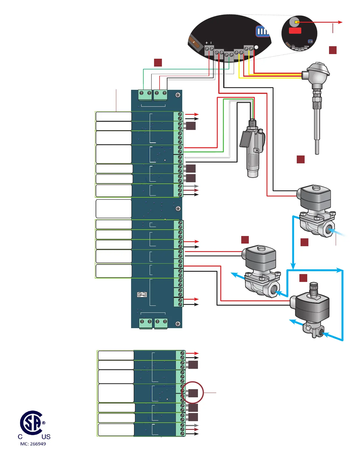
Image 1.1.1 · BMS pressure process control wiring diagram
Permissive IN
(jump closed
if not in use)
To Pilot Igniter
Ignion
Wire
Important!
I/O board
sckers. Replace
when missing.
Stack/Bath
Source Gas
7
10
8
Pilot Status OUT
(oponal)
12 or
24VDC
Power IN
Modbus RS-485
(oponal)
ESD Valve
Source
Gas
To Pilot
To Burner
Process 1 Valve
Pilot Valve
13
14
15
Image 1.1.2 · BMS temperature process control wiring diagram
Permissive IN
(jump closed
if not in use)
Note: Wiring for the temperature process control is
idencal as the pressure process control (Image 1.1.1)
except the Transducer Port should be jumpered.
Modbus RS-485
(oponal)
5
Y+ R-
POWER
VALVE
OUTRET
RS485
A B
TC1
Y+ R-
TC2
 Loading...
