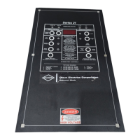
Cimco Series 21
CIMCO ELECTRONICS, INC. 26 MAIN STREET; P. O. BOX 248
www.cimcoelectronics.com WEST MIDDLESEX, PA 16159
E-MAIL: cimco@cimcoelectronics.com PHONE (724) 528-9559
FAX (724) 528-1108
Contact Cimco for details www.cimcoelectronics.com Operator Instructions-21-January 2002-Rev 4
Page 3 of 6
Series 21 with Microprocessor
(continued)
STANDARD CONNECTION INSTRUCTIONS
BACK-PLATE
INPUT POWER
CONNECT LAST TO T-11 & T-12
1.
Determine input power voltage.
2. Connect H1, H2, H3, and H4 while following instructions on the back of the instrument.
3.
The 0.25 amp fuse protects the instrument if 240 VAC is applied while the instrument is connected for 120 VAC power.
FAN POWER CONTROL
(CONNECT FIRST)
TWO OUTPUTS TOTAL
1.
Fan power relays are fail-safe.
2. Fans one output power use T-1 and T-2.
3.
Fans two output power use T-3 and T-4.
4. Each circuit rating if used alone is 30 amps, 1 HP at 120 VAC, 2 HP at 240 VAC.
5.
Total rating for both circuits together is 30 amps, 2 HP at 120 VAC, 4 HP at 240 VAC.
6. Instrument is supplied with 20 amp fuse. Maximum fuse rating is 30 amps.
7.
Additional fan controls are available with optional fourth and fifth set-point relays.
TEMPERATURE SENSORS - CONNECT SECOND
1. Non-magnetic Type E thermocouple is standard.
2. Red lead is always negative.
3.
Cut thermocouples to length.
4. Never form loop with the thermocouple leads.
5.
Strip 3/8 to 0.4 inch insulation from metal leads.
6. Use clamp on terminal block to connect thermocouples to terminal blocks on back of instrument.
7.
Do not use crimp lugs.
8. Clamp leads firmly in place.
SYSTEM GROUND
1.
Instrument ground is isolated from system ground.
2. Connect system ground to T-10.
TRIP AND ALARM RELAYS
1. Form C relays.
2.
Connects are dry.
3. Alarm relay is fail-safe.
4.
Trip relay is NOT fail-safe.
1.
Obtain permission from the transformer manufacturer before changing any programmable features.
2. Contact Cimco for programming instructions.
 Loading...