Cimco Series 21
CIMCO ELECTRONICS, INC. 26 MAIN STREET; P. O. BOX 248
www.cimcoelectronics.com WEST MIDDLESEX, PA 16159
E-MAIL: cimco@cimcoelectronics.com PHONE (724) 528-9559
FAX (724) 528-1108
Contact Cimco for details www.cimcoelectronics.com Operator Instructions-21-January 2002-Rev 4
Page 2 of 6
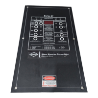
Series 21 with Microprocessor
STANDARD INSTRUCTIONS
FACE-PLATE
OPERATING STATUS
!
Power on light is green.
! Fans on light is amber (yellow).
!
Alarm on light is red.
! Trip on light is red.
DISPLAY CONTROLS
!!
MAXIMUM TEMPERATURE MEMORY (MTM)
!! PRESS READ to display MTM since last reset.
! PRESS RESET to erase MTM.
! MTM is retained indefinitely with loss of power.
!
READ OTHER PHASES
! Instrument automatically displays highest temperature input.
! Green LED indicates hottest phase.
! PRESS other buttons to read other phases.
! SYSTEM TEST
!! PRESS AND HOLD bottom left button.
! PRESS AND RELEASE bottom right button to advance test mode.
! TEST MODE SEQUENCE is described on face-plate.
! Local alarm can be silenced if desired.
! Trip relay will not turn on.
! Trip relay turns on only with input signal.
! RELEASE bottom left button when test is complete.
OPERATION CONTROLS
!! FAN MODE CONTROL LED’s indicate auto or manual control of fan power.
!
START-UP condition is AUTO.
! PRESS MANUAL ON to energize fans for continuous running.
!
PRESS AUTO to return to automatic mode.
! FAN EXERCISER (PROGRAMMABLE) will energize fans once per week.
FAIL-SAFE START-UP DEFINITION
1. At start-up, alarm and fan contacts are in “on-state”.
2.
Alarm and fan contacts change to “off-state” when power is applied or,
3. Alarm and fan relays revert to “on-state” if thermocouple is open or,
4.
Alarm and fan contacts revert to”on-state” if power is lost.
Options
! Each option has dedicated instructions.
!
Contact Cimoc if not supplied with instrument.
 Loading...