The provided document is an instruction manual and parts list for CIRCOR IMO A3D Series Pumps.
Function Description
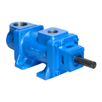
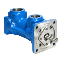
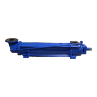
The IMO Pump Series A3D pumps are designed to meet various requirements for hydraulic, distillate, lubricating, residual, and crude oil applications. These pumps are engineered to handle a wide range of operating conditions, necessitating a variety of construction and material combinations to fulfill job requirements. The manual emphasizes that proper use requires identification of the specific pump assembly and seal arrangement, which can be determined by referring to the provided figures and tables.
Important Technical Specifications
Rotor Sizes: The A3D series pumps are available in various rotor sizes, including 106, 118, 137, 156, 187, 218, 250, 275, 312, 337, 350, and 400.
Maximum Speed (Rpm):
- Distillate Oils (Type B & H):
- 106-118: 5000 rpm
- 137: 4400 rpm
- 156: 4400 rpm
- 275: 3000 rpm
- 337 to 400: 2500 rpm
- Lube & Seal Oil (Type B & H):
- 106-118: 5000 rpm
- 137: 4400 rpm
- 156: 4400 rpm
- 275: 3000 rpm
- 337 to 400: 2500 rpm
- Lube & Seal Oil (Type F):
- 106-118: 3800 rpm
- 137: 3200 rpm
- 156: 3000 rpm
- 275: 1900 rpm
- 337 to 400: Limit
- Residual & Crude Oils (Type B & H):
- 106-118: 1800 rpm
- 137: 1800 rpm
- 156: 1800 rpm
- 275: 1800 rpm
- 337 to 400: 1800 rpm
- Residual & Crude Oils (Type F):
- 106-118: 1800 rpm
- 137: 1800 rpm
- 156: 1800 rpm
- 275: 1800 rpm
- 337 to 400: 1800 rpm
Minimum Viscosity:
- 1st Letter Designator F: 100 SSU Minimum
- 1st Letter Designator B: 33 SSU Min / 2500 SSU Max
- 1st Letter Designator H: 33 SSU Min / 15000 Max
Minimum Liquid Temperature: 0°F
Maximum Liquid Temperature:
- 1st Letter Designator F: 230°F
- 1st Letter Designator B: 180°F
- 1st Letter Designator H: 220°F
Maximum Inlet Pressure:
- 75 psig for sizes 137 thru 250
- 50 psig for sizes 275 and larger
- 10 Psig for Packing Pumps
Maximum Discharge Pressure (Continuous Duty): 500 psig
Filtration: Refer to General Instruction Manual, SRM000
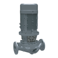
Drive: Direct or Belt For Seal Pumps Direct Only for Packing Pumps
Mounting: Mounted in any attitude
Rotation: Can be Clockwise (CW), Counter-Clockwise (CCW), or Short Lead Rotor Size.
Seal Designs (1st Letter Designator):
- B - Crane Type 21, Buna Fitted, Std. Bearing
- C - Crane Type 9, Teflon Fitted, Std. Bearing
- F - Standard Packing
- H - Crane Type 8, Teflon Fitted, Hi-Temp Bearing
- K - No Seal, Open Bearing
- L - Crane Type 2, Std. Bearing
- M - Borg BXQW, Buna Standard Bearing
- N - Borg Warner Type BX, Viton Fitted Hi-Temp Bearing
- R - Crane S8B5 Seal, Hi-Temp. Bearing
- S - Sealol, Viton Fitted, Hi-Temp Bearing
- U - Borg Seal, Hi-Temp. Bearing
- V - Crane Type 21, Viton Fitted, Std. Bearing
- W - Hi-Temperature Packing
- Z - Borg Warner Type Q, Viton Fitted, Hi-Temp. Bearing
Mounting and Casing Options (2nd & 3rd Letter Designators):
- C - Circular Mounting Flange
- H - Special Mounting Flange
- J - Carbide Seal Seat Silicon
- M - Circular Mtd. Flange, Nodular Iron Casing
- N - Nodular Iron Casing
- P - Straight Thru Inlet – 300 Lb. R.F. Flange
- R - Straight Thru Inlet – 150 Lb. R.F. Flange
- S - Steel Casing
- T - Carbide Seal Seat Tungsten
- U - Stellite Seal Seat
- X - Special Material or Construction
- Y - Metal Bellows Seal Neoprene Type 680/BXQ
Seal Seat Materials (4th Letter Designator):
- J - Carbide Seal Seat Silicon
- T - Carbide Seal Seat Tungsten
- X - Special Material or Const.
Usage Features
The manual provides general instructions for the operation and maintenance of the A3D Series pumps. It emphasizes that the manual cannot cover every possible situation and advises users to contact Imo Pump for further assistance if specific questions arise.
Ordering Instructions:
To obtain renewal parts for Series A3D pumps, users must refer to the instruction manual number and address the request to the nearest Imo Pump Division representative listed in SRM00046.
Renewal part orders should include:
- Give number of this instruction manual.
- Give pump type and serial number of pump for which part(s) is ordered.
- Give figure number(s) on which pump type and sealing design part(s) is shown.
- Give part number(s) for necessary part(s).
Safety Warnings:
- A warning is provided regarding the disassembly of mechanical seal pumps: "To prevent personnel/equipment injury, power supply to pump driver must be disconnected or positively tagged out prior to starting any disassembly procedure."
- Another critical warning states: "When inspecting/servicing shaft seal and/or bearing, power rotor can be removed as a subassembly with these components installed. Remove four (4) bearing retainer plate bolts and retainer plate, and then remove power rotor sub-assembly. If for any reason pump is disassembled further than this, it is possible idler rotor balance piston housings may fall off. These idler rotor balance piston housings MUST be properly in place at reassembly. If idler rotor balance piston housings are not properly installed on idler rotors, pump WILL experience catastrophic failure." This warning is repeated for both mechanical seal and packing pump assembly procedures, highlighting its importance.
- For packing pumps, a caution is given for startup: "When starting pump, adjust packing seepage to allow no more than eight (8) drops per minute. DO NOT over-tighten packing. Seepage from packing gland provides cooling and lubrication of packing."
Maintenance Features
The manual details comprehensive disassembly and assembly procedures for both mechanical seal and packing pumps.
General Maintenance Notes:
- Prior to pump assembly, all parts should be cleaned and inspected for nicks and burrs.
- All worn or damaged parts must be replaced.
- Imo Pump Division recommends automatic replacement of O-rings (027, 028, 038), gaskets (009), Dyna seal (007), ball bearing (049 or 015), and mechanical seal (025) when these parts are disturbed from their previously installed position.
- All parts should be coated with light lubricating oil to assist in assembly.
- Assembly procedures for all A3D pumps equipped with mechanical seals are identical except when specifically noted.
Disassembly Procedures (Mechanical Seal Pumps - Figures 3, 7, 8, 9, 10, 11):
- Close off suction and discharge piping and disconnect piping.
- Remove tubing (071) and, if applicable, check valve (078).
- Remove inlet drain plugs and drain unit. Remove pump from driver, coupling, and mounting bracket. Remove coupling hub and key (031).
- Remove inlet capscrews (004), inlet head (002), and gasket (009) or O-ring (070 or 075).
- Remove thrust cage (029) or rotor housing (024). Remove oil balance tube (026) with O-rings (027) from either thrust cage (029) or rotor housing (024).
- Remove idler balance piston housings (023) from idler rotors (021) and remove idler rotors (021) by unscrewing them from rotor housings (024).
- Remove bolts (029 or 053) with lockwashers (030 or 052). Remove thrust plate (026 or 029) and spacers (023 or 051). Remove spacer (040 or 050) from case (001).
- Remove idler rotors (021) from housing (024) bores by unscrewing idler rotors from threads of power rotor.
- Remove bolts (047 or 017) and bearing retainer (043 or 016).
- Remove power rotor (044 or 063) assembly from case (001).
- NOTE: Removal of power rotor (044 or 063) will also remove Truarc rings (042), ball bearing (049), spacer (048 or 014), sleeve (037 or 038) if applicable and mechanical seal (025).
- NOTE: Balance piston furnished as part of power rotor (044 or 063) and is not serviced separately.
- Remove gasket from bore of inboard cover (046 or 008).
- Remove inboard cover capscrews (004) and inboard cover (046 or 008) from case (001).
- NOTE: Removal of inboard cover (046) may include removal of O-ring (028) and bushing (086). Bushing (086) is locked to inboard cover (046) with Loctite retaining compound and should not be removed unless replacement is necessary.
- Remove gasket (009) from case (001).
- Remove balance piston housing (022 or 045) with O-ring (028) from case (001).
- Remove oil balance tube (026 or 036) with O-rings (027 or 038) from rotor housing (024) or balance piston housing (022 or 045) or inboard cover (046 or 008).
- Remove stop pin (006) and Dyna Seal (007) from case (001). Remove rotor housing (024) with O-ring (028) from case (001).
- Disassemble power rotor (044 or 063):
- Remove outer truarc ring (042). Press ball bearing (049) off power rotor (063). Remove inner truarc ring (042).
- If seal is J seat type, remove spacer (048 or 014) and mechanical seal stationary seat. If seal is O-ring type, remove seal seat adapter (048 or 014) with stationary seat from power rotor (044 or 063).
- Remove mechanical seal rotating assembly from power rotor (044 or 063).
- Remove sleeve (038 or 037) from power rotor (044 or 063).
Assembly Procedures (Mechanical Seal Pumps - Figures 3, 7, 8, 9, 11):
- Install O-ring (028) in groove of rotor housing (024). Install O-rings (027) on oil balance tube (026), and install oil balance tube (026) in suction end of rotor housing (024).
- Install O-rings (027 or 038) on oil balance tube (026 or 036), and install oil balance tube (026 or 036) in discharge end of rotor housing (024).
- Install assembled rotor housing (024) in case (001), aligning housing (024) to receive stop pin (006). Install stop pin (006) with Dyna seal (007) in case (001).
- Install O-ring (028) in groove of balance piston housing (022 or 045), and install balance piston housing (022 or 045) in case (001), ensuring that bore of balance piston housing (022 or 045) engages oil balance tube (026 or 036) installed in rotor housing (024).
- Install gasket (009) on case (001).
- Install inboard cover (046 or 008) on case (001) using capscrews (004 or 093). Tighten capscrews (004 or 093) to proper torque value listed in Table 2.
- Disassemble power rotor (044 or 063) as follows:
- Install sleeve (038 or 037) on power rotor (044 or 063) shaft next to piston.
- Install mechanical seal (025) rotating assembly on power rotor (044 or 063) shaft. Tighten set screw if applicable.
- If seal is J seat type, install stationary seat on power rotor (063 or 044) shaft. Then install spacer (014 or 048). If seal stationary seat is an O-ring design, be sure O-ring is installed on seal seat and then install seal in seal seat adapter (048 or 014). Be sure groove in back of stationary seat mates with pin in seal seat adapter (48 or 14).
- Install inner truarc ring (042) in groove of power rotor. Press ball bearing (049) on power rotor (063) shaft, pressing only on inner race of bearing. Install outer truarc ring (042) in groove of power rotor shaft.
- Install gasket or O-ring, based on mechanical seal design, in mechanical seal bore of inboard cover (046 or 008).
- Install assembled power rotor (044 or 063) in inboard cover (046 or 008), centering each part as it enters pump case (001).
- Install bearing retainer (043 or 016) using bolts (047 or 017). Tighten bolts (047 or 017) to proper torque value listed in Table 2.
- Install idler rotors (021) in idler bores of rotor housing (024) by engaging threads of idler rotors with threads of power rotor (044 or 063) and rotating idler rotors (021) while inserting them into rotor housing (024) bores.
- Install idler balance piston housings (023) on idler rotors (021).
- Install thrust cage (029), ensuring that bore of thrust cage (029) engages oil balance tube (026) installed in rotor housing (024).
- Install spacers (023 or 051) and thrust plate (026 or 029) on rotor housing (024) using bolts (029 or 053) and lockwashers (030 or 052). Tighten bolts (029 or 053).
- Install gasket (009) and inlet head (002) on case (001) using bolts or capscrews (004). Tighten bolts or capscrews (004) to proper torque value listed in Table 2.
- Install drain plugs which were removed during pump disassembly.
- Install key (031) and coupling hub on power rotor (044 or 063) shaft.
Disassembly Procedures (Packing Pumps - Figures 4, 5, 6):
- Close off suction and discharge piping to pump and disconnect piping.
- Remove tubing (081) from pump, ensuring that tubing (081) is not bent or flattened. Remove drain plugs (005 and 080).
- Remove pump from driver, coupling and mounting bracket. Remove coupling hub and key (031).
- Remove packing gland nuts (016) with washers (015) and remove packing gland (018).
- Using a "packing puller" or sharp pointed brass or copper rod, remove packing (017).
- Remove bolts or capscrews (004), packing box end cover (003) and gasket (009).
- Remove bolts or capscrews (004), inlet head (002) and gasket (009) from case (001).
- Remove thrust cage (029).
- Remove idler balance piston housings (023) and idler rotors (021).
- NOTE: Remove idler rotors (021) by unscrewing idler rotors from housing (024) bores.
- Remove spacer (090).
- Remove cap screws (011) and retainer plate (010).
- Remove retaining ring (008).
- Remove power rotor (019 or 063). Removal of power rotor (019 or 063) will also remove balance piston housing (022) with O-ring (028) and oil balance tube (026).
- NOTE: Balance piston (020) furnished as part of power rotor (019 or 063) and is not serviced separately.
- Remove balance piston housing (022) from power rotor (019 or 063). Remove O-ring (028) and oil balance tube (026) from balance piston housing (022).
- Remove O-ring (027) from oil balance tube (026), and remove relief valve (032) from balance piston housing (022).
- Remove stop pin (006) with Dyna seal (007) from case (001).
- Remove rotor housing (024) with O-ring (028) and oil balance tube (026) from suction end of pump case (001).
- Remove O-ring (028) and oil balance tube (026) from rotor housing (024). Remove O-rings (027) form grooves of oil balance tube (026).
Assembly Procedures (Packing Pumps - Figures 4 through 6):
- Install O-ring (028) in groove of rotor housing (024), and install rotor housing (024) in suction end of pump case (001), ensuring that bore in rotor housing (024) is aligned with stop pin (006) bore of pump case (001).
- Install stop in (006) with Dyna seal (007) in pump case (001) and rotor housing (024).
- Install O-rings (027) in grooves of oil balance tube (026) and install oil balance tube (026) in bore of suction end of rotor housing (024).
- Install O-ring (028) in groove of balance piston housing (022), and install balance piston housing (022) on power rotor (019 or 063) shaft.
- Install relief valve (032) in balance piston housing (022). Install O-rings (027) in grooves of oil balance tube (026).
- Install oil balance tube (026) in bore of balance piston housing (022).
- Install power rotor (019 or 063) assembly in bore case (001), ensuring that oil balance tube (026) engages bore of rotor housing (024).
- Install retaining ring (008) in groove of case (001).
- Install retainer plate (010) using capscrews (011).
- Install spacer (090).
- Install gasket (009) and packing box end cover (003) using bolts or capscrews (004). Tighten bolts or capscrews (004) to proper torque value listed in Table 3.
- Install packing (017) rings in packing bore of packing box end cover (003). Joints of packing (017) ring to be staggered and hard and soft rings alternately inserted, beginning with hard ring of packing.
- Install packing gland (018). Install washer (015) and nut (016) on packing gland screw (014) and tighten nut (016) hand tight.
- Install idler rotors (021) into rotor housing (024) idler rotor bores by engaging threads of idler rotors with threads of power rotor (019 or 063) and rotating idler rotors (021) while inserting them into rotor housing (024).
- Install idler balance piston housings (023) on idler rotors (021).
- Install thrust cage (029), ensuring that bore in thrust cage (029) engages oil balance tube (026) installed in rotor housing (024).
- Install gasket (009) and inlet head (002) on case (001) using bolts or capscrews (004). Tighten bolts or capscrews (004) to proper torque value listed in Table 3.
- Install key (031) and coupling hub on power rotor (019 or 063) shaft.
- Install drain plugs (005 or 080).
- Install tubing (081) and fittings in proper position.
- Connect pump to mounting bracket and coupling. Align pump with driver as described in Manual CA-1.
The manual also includes detailed diagrams (Figures 3-11) illustrating the typical pump assembly drawings for different rotor sizes and seal types, as well as seal installation variations. A comprehensive list of materials (Table 4) is provided, detailing part descriptions and item numbers, with notes on minor and major kit items and specific part applicability based on rotor size and assembly figures.