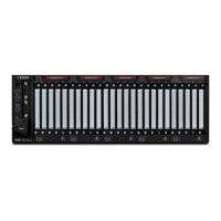
CH2 Connector Saver
Allows quick and repeated connections to the Cirris® CH2 Tester.
Installing the Connector Saver
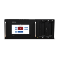
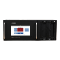
Using a straight edge, align the top and side
edges of the Connector Saver Frame Assembly
to the top and side edges of the corresponding
CH2 Scanner. Make sure the top indicator is up.
Tools required for Install:
Before You Start
When properly aligned the
top pins insert in the second
row of the CH2 Scanner
connector as shown below.
First row
Second row
Connector Saver
Frame Assembly
Straight edge
Straight Edge
Medium Phillips
Screw Driver
Frame Assembly
Six #4 x 3/8”
Screws
Lever
Assemblies
Hold Down
Plates
ADCS-C2
Each CH2 Connector Saver kit should
include:
Top indicator
Six M2.5 x
5mm Screws