4
Installing the High-Density Electrical Interface Assemblies on the Cisco ONS 15310-MA
78-17418-01
Install the High-Density EIAs
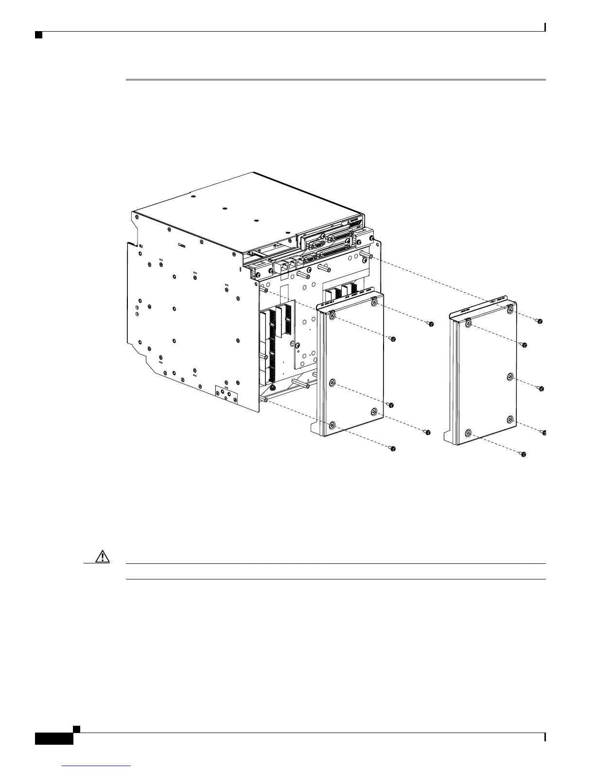
Step 1 Remove the blank sheet metal covers. Use a Phillips screwdriver to remove the five screws holding each
sheet metal cover in place.
Figure 3 shows the screw locations of the sheet metal covers installed on the A- and B-side of the ONS
15310-MA.
Figure 3 Blank Sheet Metal Covers
Step 2
Determine which high-density EIA is designed for installation on the B Side and which is designed for
installation on the A Side (Figure 2 on page 3).
Step 3 Align the connectors on the EIA you want to install with the mating connectors on the backplane, using the
plastic guide posts on the connectors.
Caution Do not firmly apply pressure to the EIA; this could damage the EIA and backplane connectors.
Step 4 Seat the EIA as flat as possible by gently exerting enough pressure with your hands to only partially seat the
connectors. Do not try and fully insert the EIA.
Step 5 Locate the two jack screws on the EIA, which are found on the opposite corners (Figure 2 on page 3). (For
example, on the B-side EIA, the screws are located in the top right and bottom left corners.)
Step 6 Starting with either jack screw, tighten the thumb screw turn five full turns, then turn the other thumb
screw five full turns (Figure 4). Alternate between the jack screws until the EIA is full seated onto the
chassis and the jack screws are hand tight. The EIA is fully mated when both jack screws are fully threaded
into the chassis.
Blank sheet metal cover
installed on the B Side
Blank sheet metal cover
installed on the A Side