Installing and Upgrading Internal Modules and FRUs in Cisco 1900 Series ISRs
Modules Internal to the Cisco 1941 Router
7
Installing and Upgrading Internal Modules and FRUs in Cisco 1900 Series ISRs
Closing the Chassis
Step 1 Make sure that the router is turned off and is disconnected from AC power.
Step 2 Slide the top of the router (which is facing up toward you) back onto the bottom of the router.
Step 3 Turn the router upside down, and rest the top of the router on a flat surface.
Step 4 Use the Phillips screwdriver to install the screws that hold the top of the of the case to the chassis, as
shown in Figure 1. Torque the screws to 6 to 8 in-lb (0.68 to 0.90 N-m).
Step 5 Turn the router back to its original position (top up).
Step 6 Reconnect the AC power.
Locating Modules
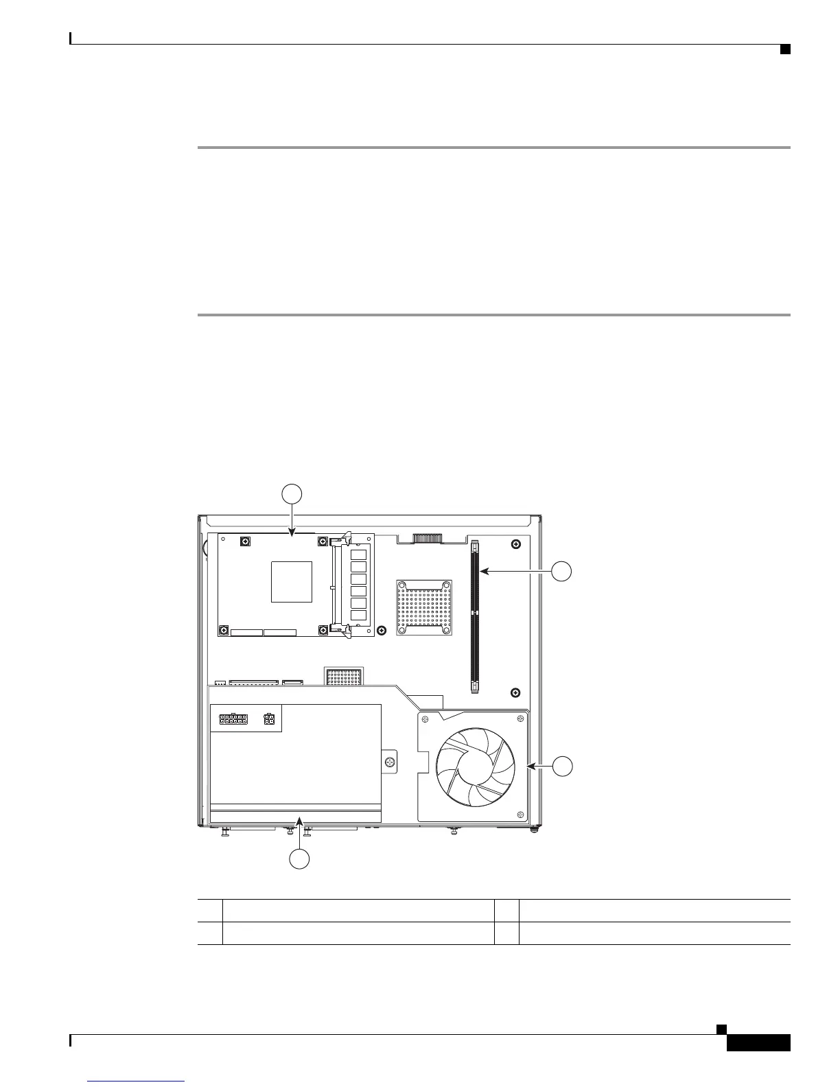
Figure 3 shows where the locations of the ISM, unbuffered dual inline memory module (UDIMM),
power supply and blower located in the Cisco 1941 chassis.
Figure 3 Cisco 1941 Internal Modules
1 ISM
1
1. In the 1941W this is a WLAN module. It is not a user removable or installable.
2 UDIMM
3 Blower 4 Power supply
251368
2
1
4
3