4
Installation
• Modem for remote configuration (if required)
• Console terminal (configured for 9600 baud, 8 data bits, no parity, and 2 stop bits)
if future reconfiguration is desired
Information on Mounting the Router on a Rack or Wall
Rack and wall mounting procedures are described in a separate publication included
with the optional rack mount kit. If you intend to rack mount the router, do so before
making the external connections.
Preparing for External Connections
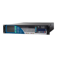
Following are the procedures for making external connections to the router. Figure 1
shows the rear panel of the router with the following connectors:
• Ethernet DB-15 (2102) or Token Ring DB-9 (2202)
• Serial DB-50 (1)
• Console RS-232
• Auxiliary RS-232
• AC power cable
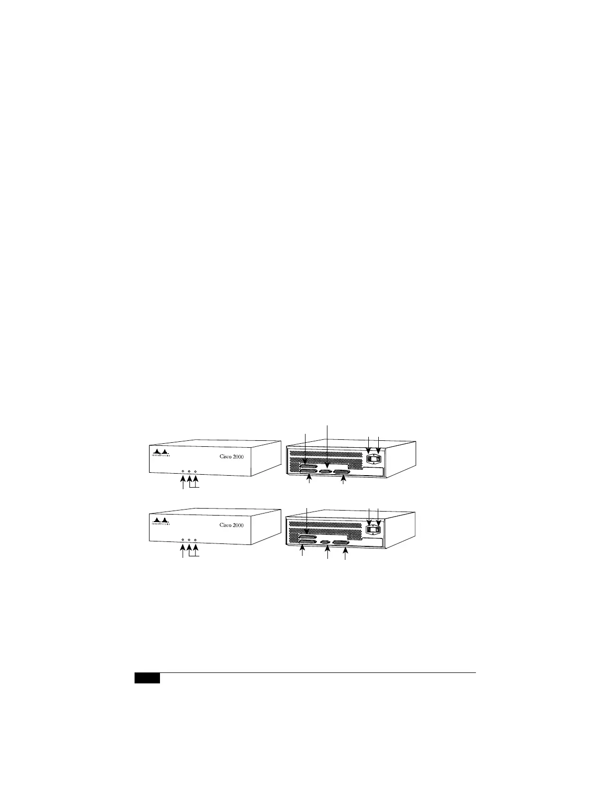
Figure 1 Router Front and Rear View—Models 2102 and 2202
Ethernet port
Power On/Off switch
AUX port (DB-25)
Console port
(DB-25)
Serial port
System OK light
OK
ETHERNET
SERIAL
Interface activity
indicator lights
OK
TOKEN RING
SERIAL
Power
On/Off switchConsole port (DB-25)
Token
Ring
port
AUX
port
(DB-25)
Serial (V2)
port
H1958
2102
2202
System OK light
Interface activity
indicator lights