9
Cisco 2811 and Cisco 2821 Integrated Services Router FIPS 140-2 Non Proprietary Security Policy
OL-8663-01
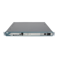
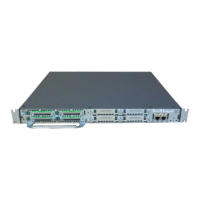
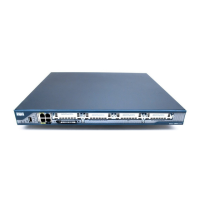
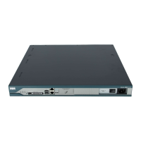
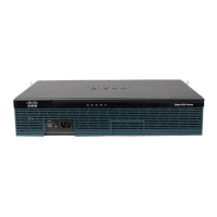
Cisco 2811 and Cisco 2821 Routers
Table 5 and Table 6 provide more detailed information conveyed by the LEDs on the front and rear panel
of the router:
Table 7 describes the meaning of Ethernet LEDs on the front panel:
Table 5 Cisco 2821 Front Panel Indicators
Name State Description
System Power Off
Blinking Green
Solid Green
Solid Orange
Power off
ROMMON mode
Operating normally
System Error Detected
Auxiliary Power Off
Solid Green
Solid Orange
-48V PS and RPS not present
-48V PS or RPS present and functional
-48V PS or RPS present and failure detected
Activity Off
Blinking Green
Solid Green
No interrupts or packet transfer occurring
System is servicing interrupts
System is actively transferring packets
Compact Flash Off
Solid Green
No ongoing accesses, eject permitted
Device is busy, do not eject
Table 6 Cisco 2821 Rear Panel Indicators
Name State Description
PVDM2 Off
Solid Green
Solid Orange
PVDM2 not installed
PVDM2 installed and initialized
PVDM2 installed and initialized error
PVDM1 Off
Solid Green
Solid Orange
PVDM1 not installed
PVDM1 installed and initialized
PVDM1 installed and initialized error
PVDM0 Off
Solid Green
Solid Orange
PVDM0 not installed
PVDM0 installed and initialized
PVDM0 installed and initialized error
AIM1 Off
Solid Green
Solid Orange
AIM1 not installed
AIM1 installed and initialized
AIM1 installed and initialized error
AIM0 Off
Solid Green
Solid Orange
AIM0 not installed
AIM0 installed and initialized
AIM0 installed and initialized error