4-8
NEBS Level 3 and ETSI Compliance Kit Installation Guide for Cisco 3620, Cisco 3640, and Cisco 3660 Routers
78-5450-06 B0
Chapter 4 Installation on Cisco 3660 Routers
Installing the Alarm Terminal Block
Follow this procedure to install the alarm terminal block (see Figure 4-10) in the Cisco 3660 router alarm
port:
Step 1 Turn OFF power to the router. However, to channel ESD voltages to ground, do not unplug the power
cable.
Step 2 Use 12- or 14-AWG copper wires to connect DC-input power to the terminal blocks.
Step 3 Strip the wire shielding so that approximately 0.38 in. (9.7 mm) of each wire is exposed.
Figure 4-10 Alarm Terminal Block
Step 4
Press the orange-colored release and insert a wire into a receptacle of the alarm terminal block. Two of
the three receptacles must have wires installed (see Table 4-1). The spring-loaded connector retains the
wires.
Note Always wire the P terminal and one of the other (NO and NC) terminals.
Note To remove wires, press the orange-colored release next to each receptacle.
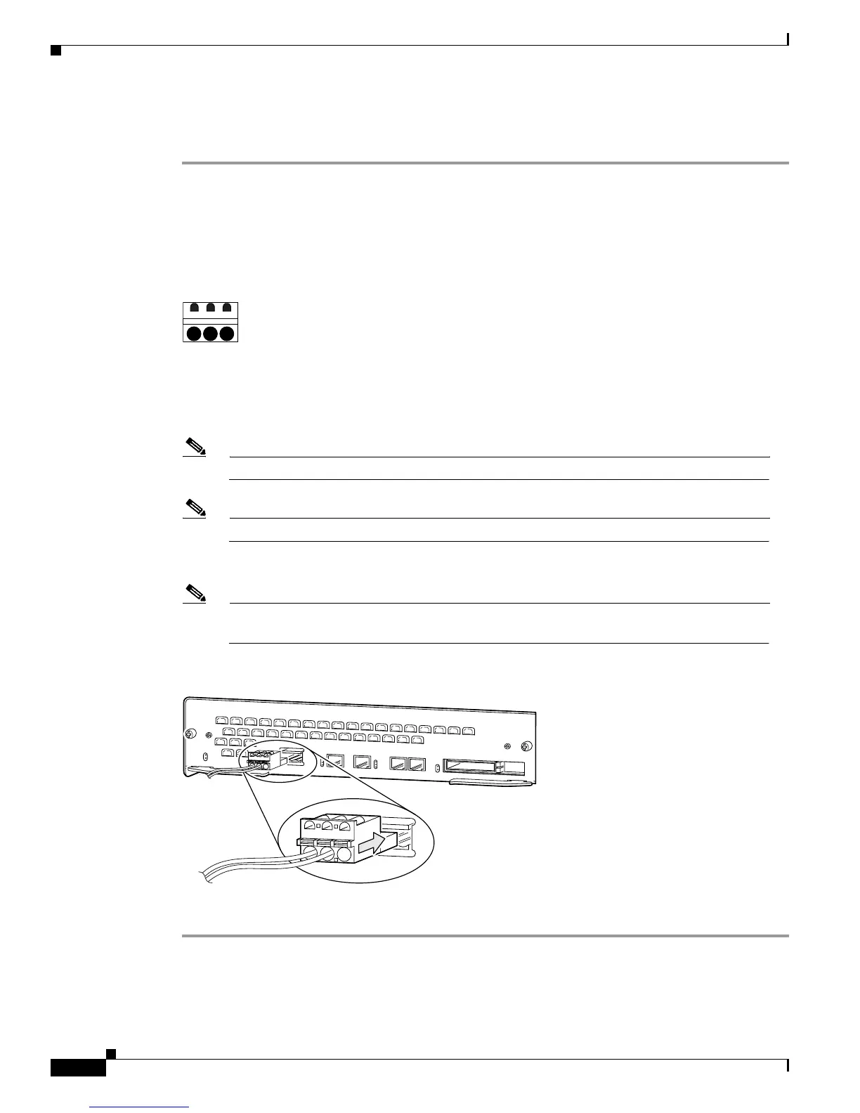
Step 5 Plug the alarm terminal block into the alarm port on the Cisco 3660 chassis. (See Figure 4-11.)
Note Connect the alarm terminal block to either an AC power source rated maximum 25 VAC and
5A current rating, or a DC power source rated maximum 30V and 5A current rating.
Figure 4-11 Connecting the Alarm Terminal Block to the Alarm Port
Step 6
Reinstall network cables, and turn ON power to the router.
22661
NO P NC
22861
V
C
C
O
K
S
Y
S
T
E
M
F
D
X
L
IN
K
1
0
0
M
b
p
s
F
D
X
1
0
L
IN
K
1
0
0
M
b
p
s