6 Upgrading Cisco 4500, Cisco 4500-M, Cisco 4700, and Cisco 4700-M Memory
Accessing the Internal Components of the Router
Removing the Component Tray from a Chassis with a Safety Latch
Take the following steps to remove the component tray from a chassis with a safety latch:
Step 1 Turn OFF the system power.
Step 2 Attach your ESD-preventive wrist strap.
Step 3 Remove all network and power cables.
Step 4 If you have a DC-powered router, take these steps to remove the power cables:
Warning Before performing any of the following procedures, ensure that power is removed from
the DC circuit. To ensure that all power is OFF, locate the circuit breaker on the panel board that
services the DC circuit, switch the circuit breaker to the OFF position, and tape the switch handle of
the circuit breaker in the OFF position.
• Use a screwdriver to loosen the captive installation screws on the terminal block cover.
• Lift and remove the terminal block cover.
• Use a screwdriver to remove the three power leads from the terminal block in the
following order: negative, positive, then ground.
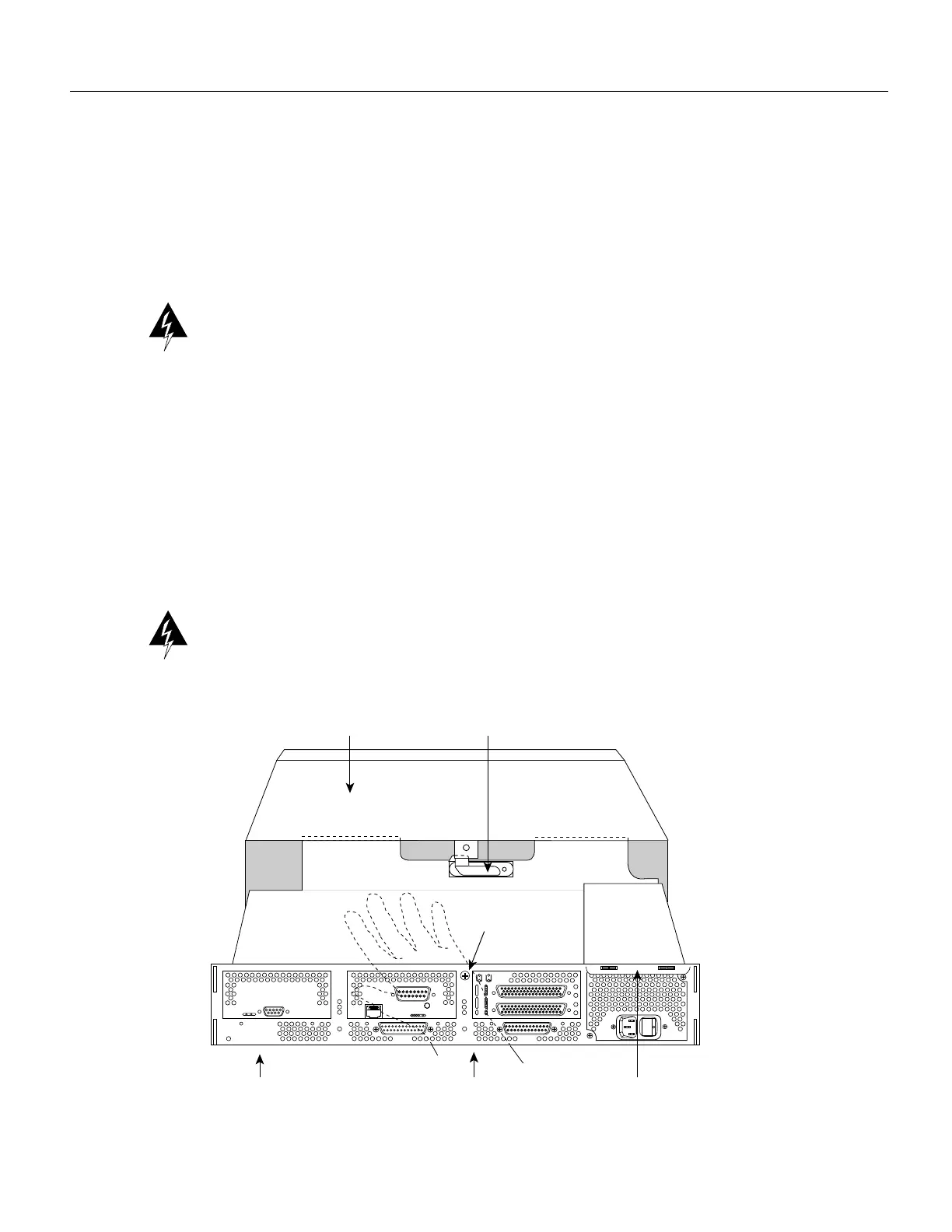
Step 5 Loosen the nonremovable chassis release screw on the rear panel of the chassis. (See
Figure 3.)
Step 6 Pull on the handle located on the upper right corner of the chassis to slide the component
tray out of the chassis shell until the safety latch catches. (See Figure 3.)
Warning Before releasing the safety latch, support the component tray from underneath, either on
your work surface or with your hands, to prevent personal injury. (See Figure 3.)
Figure 3 Component Tray Removal for Chassis with a Safety Latch
Rear of the chassis
Handle
AUX
CONSOLE
INPUT 100-240VAC 50/60HZ 3.0-1.5 AMPS
Safety latch tab
Hand supporting
component tray
H1965
Chassis shell
Chassis release
screw
 Loading...


