6 Cisco 4000 Series Rack-Mount and Wall-Mount Installation
Preparing the Chassis for Rack-Mounting or Wall-Mounting
Step 7 Set the component tray on your work surface.
Step 8 Remove the plastic front panel from the front of the chassis shell by pulling it straight out
using both hands.
Removing the Component Tray from a Chassis without a Safety Latch
Warning Hazardous voltages may exist in or near the power supply, so use extreme caution when
working near the power supply. Before starting any of these procedures, turn OFF power to the
system, unplug the power cord, disconnect any cables at the ports, and attach your ESD-preventive
wrist strap.
Take the following steps to remove the component tray from a chassis without a safety latch:
Step 1 Turn OFF the system power.
Step 2 Attach your ESD-preventive wrist strap.
Step 3 Remove all network and power cables.
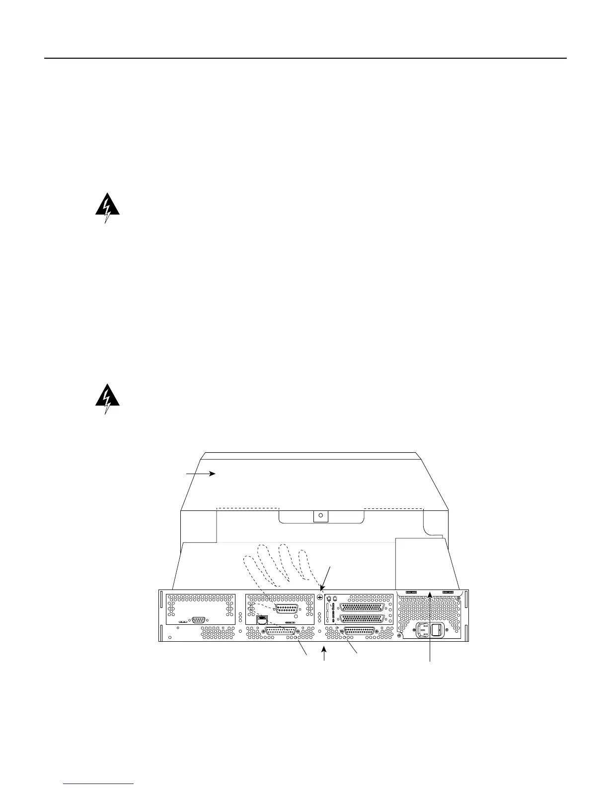
Step 4 Loosen the nonremovable screw in the back of the router chassis. The screw is labeled
“Chassis release screw” in Figure 3.
Warning Support the component tray from underneath, either on your work surface or with your
hands, to prevent it from falling.
Figure 3 Component Tray Removal for Chassis Without a Safety Latch
AUX
CONSOLE
INPUT 100-240VAC 50/60HZ 3.0-1.5 AMPS
H2899
Rear of chassis
Handle
Support the component
tray with your hand
Chassis shell
Chassis release
screw

 Loading...


