78-5296-02 10/02/98 Hardware Description 1
Cisco 6200 User Guide 1-7
The following fixtures are present on the front panel of each PEM:
• A green LED that comes on to indicate that –48 VDC power is available to the chassis
• A circuit breaker
Note To turn off a Cisco 6200 that has two PEMs, you must flip the circuit breakers on both
PEMs to OFF (0).
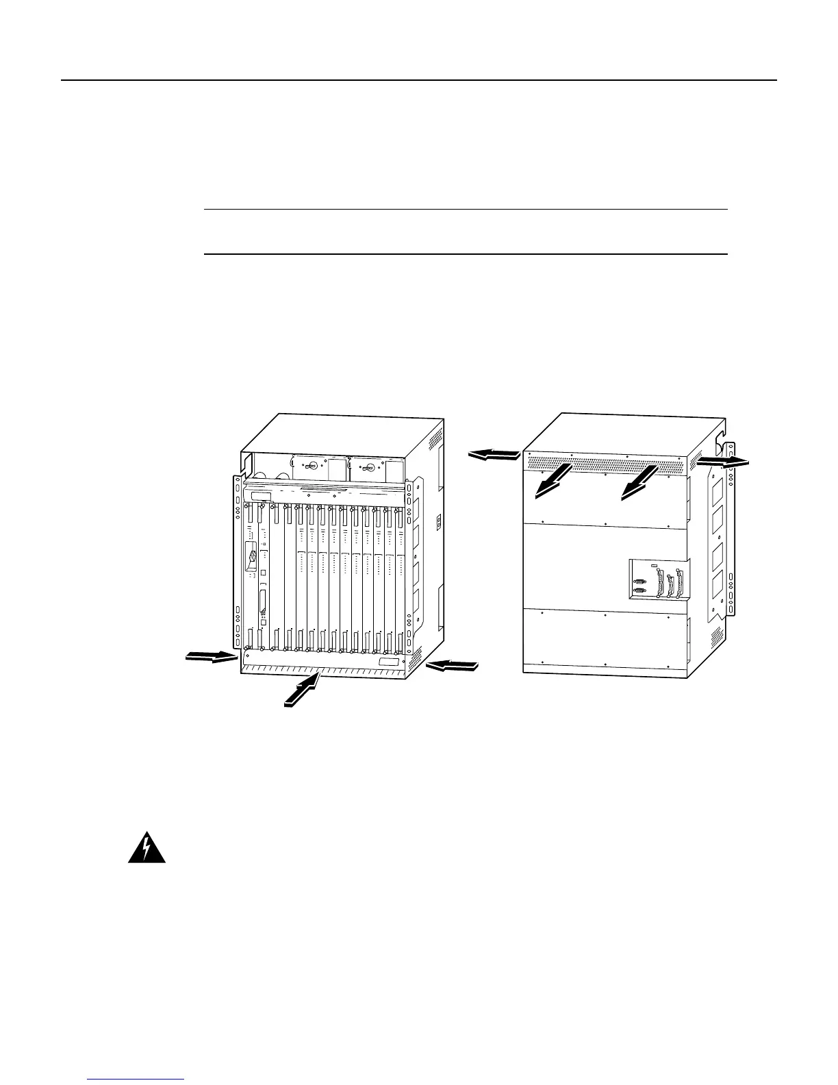
1.2.5 Cooling Vents
The cooling vents are located on the sides, front, and back of the Cisco 6200 chassis, as shown in
Figure 1-4. Air flows in at the bottom of the chassis, and flows out at the top. Do not obstruct the
intake and exhaust vents in any way.
Figure 1-4 Air Flow Through Intake and Exhaust Vents
1.2.6 DSLAM Specifications
Table 1-1 lists the specifications of the Cisco 6200 DSLAM. Table 1-2 lists standards and
certifications for the Cisco 6200 DSLAM.
Warning To prevent a Cisco 6200 system from overheating, do not operate it in an area that exceeds the
maximum recommended ambient temperature of 131˚F (55˚C).
12687