17
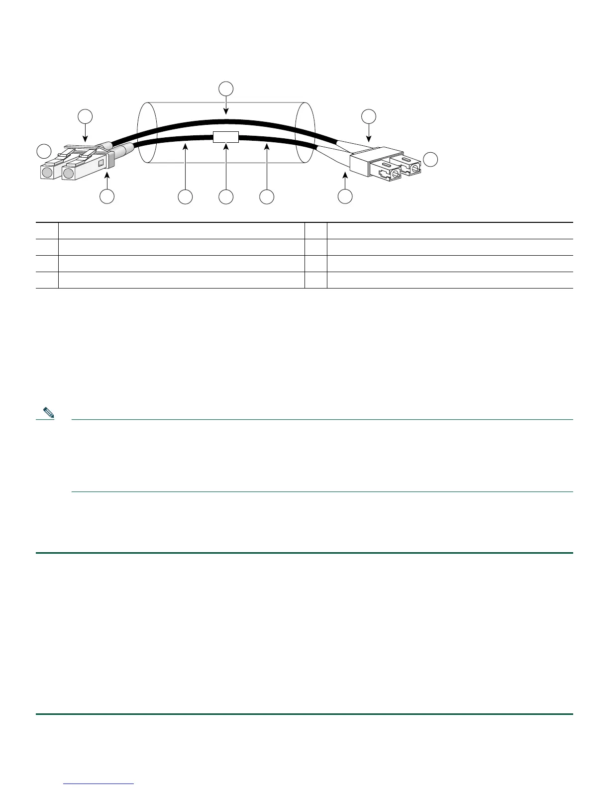
Figure 14 Mode-Conditioning Patch Cord Assembly for an SFP Module
The mode-conditioning patch cord assembly is composed of duplex optical fibers, including a single-mode-to-multimode offset
launch fiber connected to the transmitter, and a second conventional graded-index multimode optical fiber connected to the
receiver. The use of a plug-to-plug patch cord maximizes the power budget of multimode 1000BASE-LX and 1000BASE-LH
links.
The mode-conditioning patch cord is required to comply with IEEE standards. The IEEE found that link distances could not be
met with certain types of fiber-optic cable cores. The solution is to launch light from the laser at a precise offset from the center,
which is accomplished by using the mode-conditioning patch cord. At the output of the patch cord, the SFP-GE-L= is compliant
with the IEEE 802.3z standard for 1000BASE-LX.
Note We strongly recommend cleaning optical fiber connections before attaching cables to equipment. See the
Inspection and Cleaning Procedures for Fiber-Optic Connections
document at
http://www.cisco.com/en/US/tech/tk482/tk876/technologies_white_paper09186a0080254eba.shtml
and the
Compressed Air Cleaning Issues for Fiber-Optic Connections
document at
http://www.cisco.com/en/US/tech/tk482/tk611/technologies_white_paper09186a00801b08da.shtml.
Figure 14 shows
one type of mode-conditioning patch cord.
Attach the Mode-Conditioning Patch Cord
To use a mode-conditioning patch cord, follow these steps:
Step 1 If you have not already done so, and the mode-conditioning patch cord has been in use, we strongly recommend
cleaning optical fiber connections before attaching cables to equipment.
For information about cleaning fiber-optic cable connectors and receptacles, see the
Inspection and Cleaning Procedures for Fiber-Optic Connections
document at
http://www.cisco.com/en/US/tech/tk482/tk611/technologies_white_paper09186a00801b08da.shtml and the
Compressed Air Cleaning Issues for Fiber-Optic Connections document at
http://www.cisco.com/en/US/tech/tk482/tk611/technologies_white_paper09186a00801b08da.shtml.
Step 2 Attach a mode-conditioning patch cord to the SFP module. (See Figure 14.)
Step 3 Attach the network ends of your mode-conditioning patch cord to the appropriate 1000BASEX equipment in your
building cable plant.
Ensure that you connect the TX and RX ports on one end of the patch cord to the RX and TX ports (respectively) on
the other end. Connect TX to RX and RX to TX.
1
Gray color identifier
5
Single-mode bar
2
To Gigabit Ethernet interface
6
Offset
3
Blue color identifier
7
Beige color identifier
4
Multimode bar
8
To cable plant
/ / / /
/ /
TX
Offset
RX
84159
1 7
2
3 7
4
8
65 4