53
Replace the Port Adapter or Service Adapter
The port adapter or service adapter ships installed. These instructions are provided for future use. Cabling information is
included with the specific port adapter documentation.
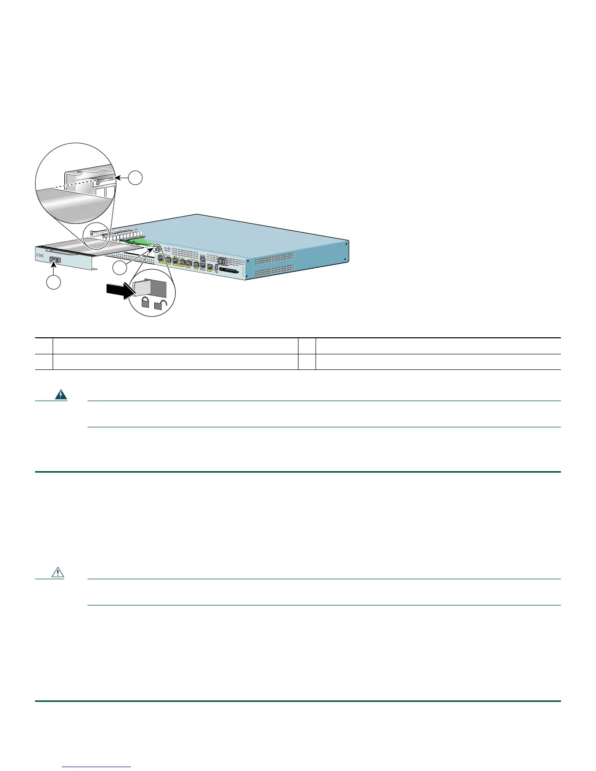
Figure 42 Removing and Installing the Port Adapter
Warning
During these procedures, wear grounding wrist straps to avoid ESD damage to the card. Do not directly touch the
backplane with your hand or any metal tool, or you could shock yourself.
Statement 94
Before removing any port adapter, gracefully shut down the interface so that there is no traffic running through the port adapter
when it is removed. Removing a port adapter while traffic is flowing through the ports can cause system disruption.
Step 1 Attach an ESD-preventative wrist strap between you and an unpainted chassis surface.
Step 2 Disconnect all cables from the port adapter.
Step 3 Remove the port adapter from the chassis slot by sliding the port adapter lever to the unlocked position.
Step 4 Grasp the handle and pull the port adapter or port adapter blank panel from the router.
Step 5 Locate the port adapter slot guides inside the Cisco 7201 router. They are near the top, and are recessed about one-half
inch.
Caution The port adapter must slide into the slot guides under the chassis lid. Do not allow the port adapter components to come
in contact with the system board or the port adapter could be damaged.
Step 6 Carefully slide the port adapter into the port adapter slot and seat it. When installed, the port adapter input/output
panel should be flush with the face of the router.
Step 7 Move the port adapter lever to the locked position.
Step 8 Reconnect any cables, including the port adapter and power cables, and place the cables through any cable-management
bracket or power cable-retention clip.
Step 9 Power on the router by turning the power switch to the on (O) position.
1
Port adapter lever
3
Port adapter slot guide
2
Port adapter
170872
A
L
A
R
M
R
J4
5
E
N
L
IN
K
T
X
R
X
G
B
IC
G
IG
AB
IT
E
T
HE
RN
E
T
0
/
2
R
J4
5
E
N
L
IN
K
TX
R
X
G
B
IC
G
IG
A
B
IT
E
T
H
E
R
N
E
T
0
/0
R
J4
5
E
N
L
IN
K
T
X
R
X
G
B
IC
G
IG
A
B
I
T
E
T
H
E
R
N
E
T
0/1
C
IS
C
O
730
1
S
L
O
T
1
C
O
N
S
O
L
E
A
U
X
C
O
M
P
A
C
T
FL
A
S
H
S
T
A
T
U
S
1
0
0
-2
4
0
V
,
2
A
,
5
0/
6
0
H
z
24
V
=
9
A
, 4
8
-
6
0
V
=
5
A
G
E
0
/
0
G
E
0
/1
G
E
0
/2
G
E
0
/3
A
U
X
C
O
N
S
O
L
E
M
N
G
M
N
T
U
S
E
O
N
L
Y
F
E
L
I
N
K
0
F
E
0
/0
R
J
4
5
S
F
P
S
F
P
S
F
P
S
F
P
L
IN
K
/
A
C
T
V
A
L
A
R
M
P
W
R
O
K
S
T
A
T
U
S
C
F
A
C
T
V
COMPACT FLASH
L
IN
K
/
A
C
T
V
R
X
T
X
L
IN
K
/
A
C
T
V
L
I
N
K
/
A
C
T
V
R
X
T
X
E
N
R
J
4
5
E
N
ENABLED
R
X
C
E
L
L
S
R
X
C
A
R
R
IE
R
R
X
A
L
A
R
M
ATM
2
3
1
Cisco 7201