47
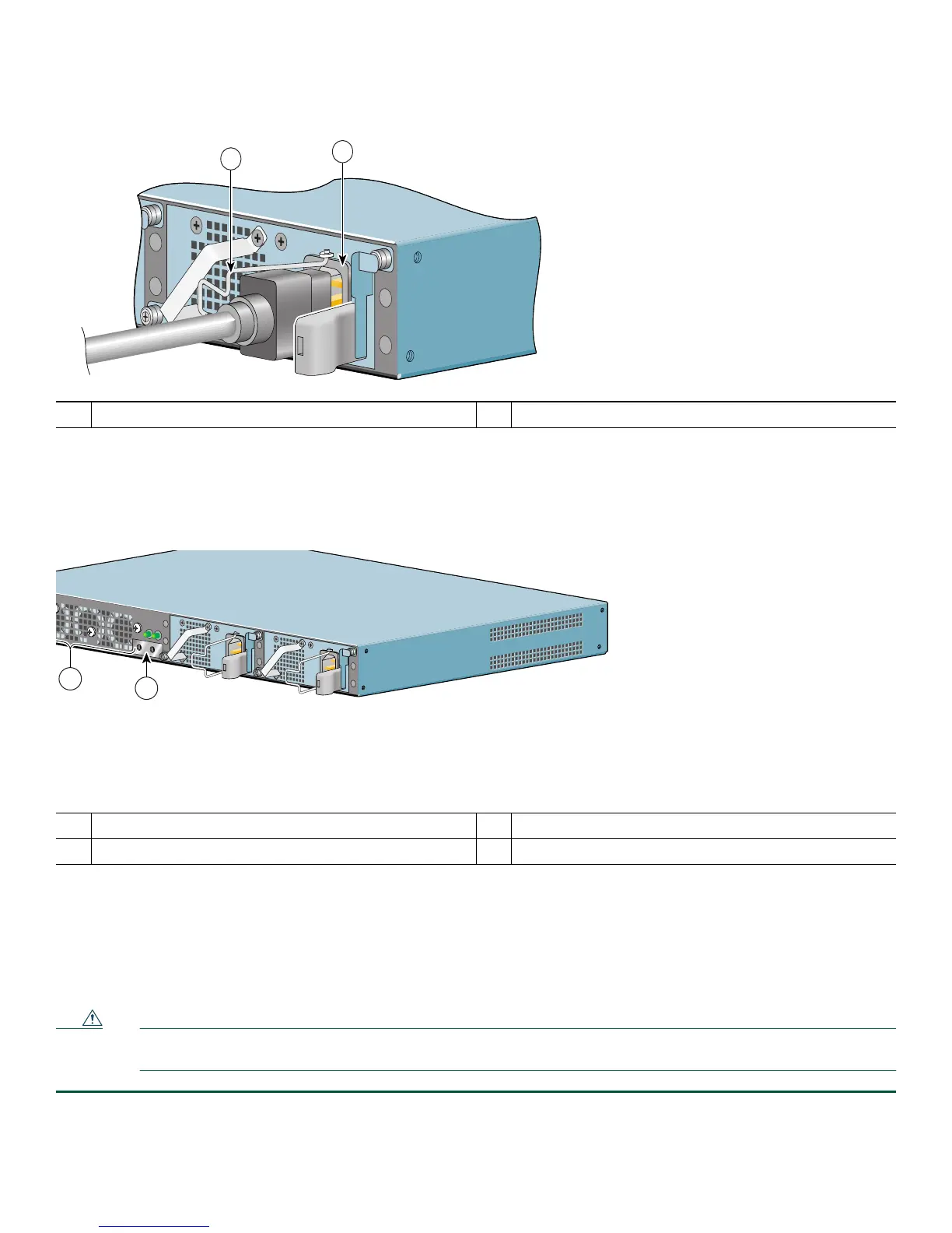
Figure 36 Removing the AC Power Cable
Step 2 Swing the cable-retention clip to the left.
Step 3 Unplug the AC power cable from the power supply.
Figure 37 Removing the AC Power Supply
Step 4 Move the power up restrictor to the left to gain access to the upper power supply captive installation screw.
Step 5 Unscrew the upper power supply captive installation screw while holding the power up restrictor to the left, then release
the power up restrictor.
Step 6 Unscrew the lower power supply captive installation screw.
Step 7 Grasping the captive installation screws, pull the power supply from the chassis.
Caution To ensure adequate airflow across the router power supplies, a power supply must be installed in each power supply
bay.
1
AC power receptacle
2
AC power cable-retention clip
1
Power up restrictor
3
Lower power supply captive installation screw
2
Upper power supply captive installation screw
PWR
SLOT 2
158677
1
2
170934
PWR
SLOT 2
PWR
SLOT 1
PWR
SLOT 1 OK
L
Y
C
O
N
N
E
C
T
IO
N
. A
L
L
C
O
N
N
E
C
T
IO
N
S
M
U
S
T
B
E
R
E
M
O
V
E
D
T
O
D
E
-E
N
E
R
G
IZ
E
T
H
E
U
N
IT
PWR
SLOT 2 OK
2
1