5-34
Cisco 7600 Series Router Installation Guide
OL-4503-24
Chapter 5 Removal and Replacement Procedures
Removing and Replacing the Power Supply
Warning
Voltage is present on the backplane when the system is operating. To reduce risk of an electric shock,
keep hands and fingers out of the power supply bays and backplane areas.
Follow these steps to remove a DC-input power supply:
Step 1 Verify that power is off to the DC circuit connected to the DC-input power supply you are removing.
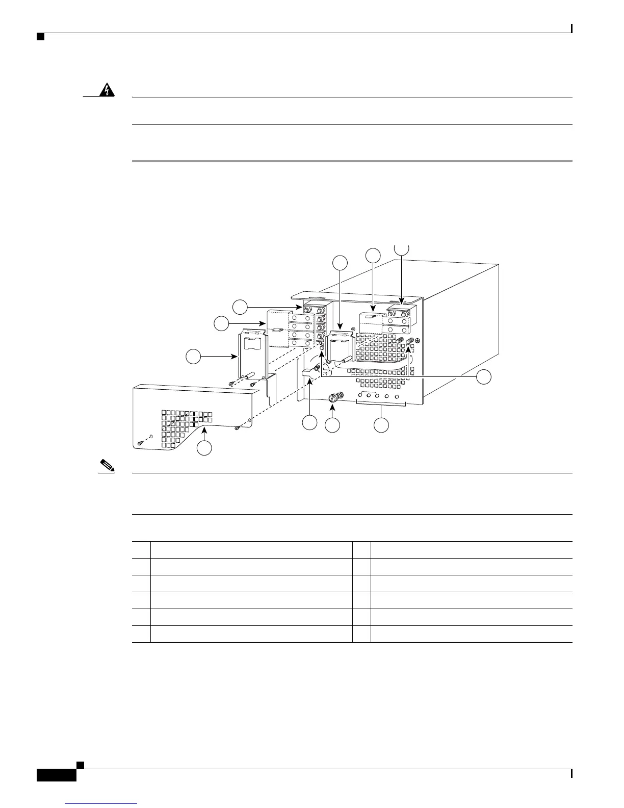
Step 2 Turn the power switch to the Off (0) position on the power supply you are removing (Figure 5-38).
Turning the power switch off also disengages a pawl that unlocks the power supply from the chassis.
Figure 5-38 DC-Input Front Panel for 4000-W DC-Input Power Supply
Note Figure 5-38 shows PWR-4000-DC with an outer terminal block cover; an earlier version of this power
supply does not have an outer terminal block cover. To order a retrofit kit use part number
CVR-4000DC-TERM=.
Step 3 Remove the two A4 screws securing the outer terminal block cover, and remove the cover from the power
supply (Figure 5-38).
Step 4 Cut any cable tie-wraps being careful not to cut the DC-input wires.
1 Inner terminal block cover 7 Power switch
2 Plastic insulator 8 Outer terminal block cover
3 DC power cable terminal block 2 (TB2) 9 Inner terminal block cover
4 Ground 10 Plastic insulator
5 Status LEDs 11 DC power cable terminal block 1 (TB1)
6 Captive installation screw
IN
P
U
T O
K
FA
N
O
K
O
U
TP
U
T
F
AIL
I
0
101397
1
3
2
5
11
6
1
10
+
V
E-1
-
VE
-1
+
V
E
-2
-
VE
-2
+
VE
-3
-
V
E-3
8
7
9
4
2



 To Next Page