5-43
Cisco 7600 Series Router Installation Guide
OL-4503-24
Chapter 5 Removal and Replacement Procedures
Removing and Replacing the Power Supply
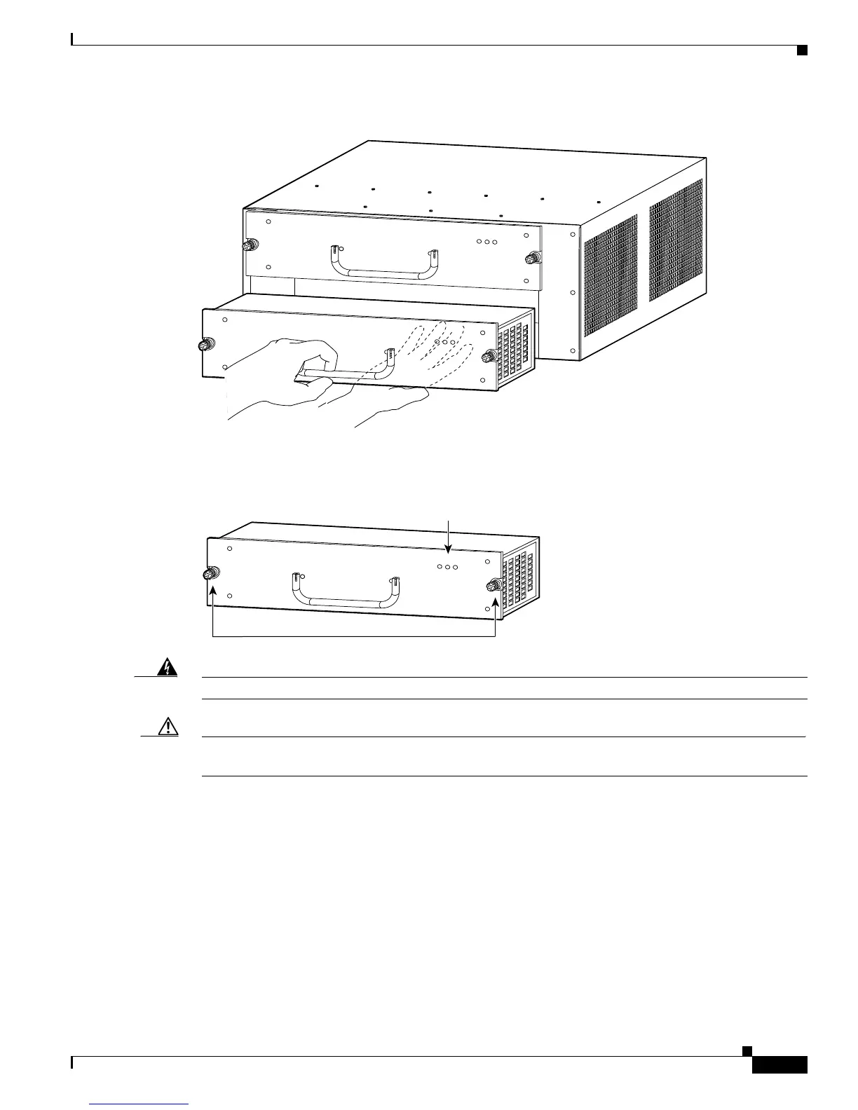
Figure 5-46 Handling the Power Supply
Step 4
Tighten the power supply captive installation screws (Figure 5-47).
Figure 5-47 Power Supply Captive Installation Screws
Warning
Power supply captive installation screws must be tight to ensure protective grounding continuity.
Caution In a system with dual power supplies, connect each power supply to a separate input line. In case of a
line failure, the second source will most likely still be available.
Step 5 Verify that all connections to the DC PEM are secure.
Step 6 Remove the tape from the circuit breaker switch handle, and restore power by moving the circuit breaker
switch handle to the On (|) position.
Step 7 Verify power supply operation by checking that the power supply front panel LEDs are in the following
states:
• INPUT OK LED is green
• FAN OK LED is green
• OUTPUT FAIL LED is not lit
63032
IN
PUT
OK
FAN
O
K
OUTPU
T
FAI L
INP
UT
OK
FAN
O
K
OUTPU
T
FAI L
63183
IN
PU
T
O
K
FAN
OK
O
U
TPUT
FA
IL
Captive installation screws
Status LEDs



 To Next Page