4-17
Cisco ASA 5585-X Adaptive Security Appliance Hardware Installation Guide
OL-22567-02
Chapter 4 Maintenance and Upgrade Procedures
Removing and Installing the Power Supply Module
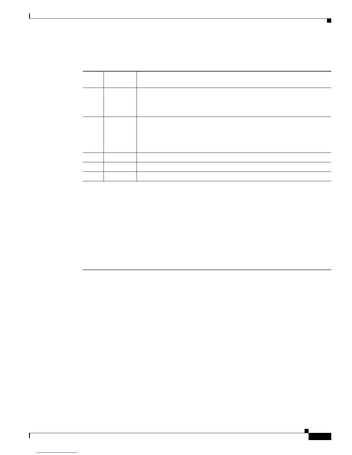
Table 4-4 describes the DC power-supply module indicators and power-switch position labels.
Installing the DC Power Supply Module
The DC power-supply module has a 1150-W output with three DC voltage outputs of 50 V, 12.25 V, and
3.35 V. The module operates between -40.5 to -72 VDC. The power-supply module shares current on the
50V and 12.25 V outputs, and can only be used in a dual (redundant) hot-pluggable configuration. The
DC power-supply module operates from a single 40 A DC input circuit with at full output load of 1150
W, -40.5 VDC input, and does not exceed 33 A.
To install a DC power-supply module in the ASA 5585-X, follow these steps:
Step 1 Remove existing modules from the appliance:
a. If you are replacing AC power with DC power, remove both modules from the appliance (fan module
and power supply module, or both power supply modules) as shown in Step 1 through Step 4 in
Removing and Installing an AC Power Supply Module, page 4-13. Continue with Step 2.
b. If you are replacing a failed DC power-supply module with a new DC power-supply module, follow
the steps in Removing the DC Power Supply Module, page 4-24, and then continue with Step 2.
Table 4-4 DC Power Supply Module Indicators
Figure
Label Indicator Description
1 IN OK Status of power-supply module:
• Unlit—No DC power cables connected, or DC power switch is off.
• Green—DC power cables connected and DC power switch is on.
2 FAN OK Indicates status of fan module
• Unlit—Fan module failure, or DC power switch is off.
• Green—DC power cables connected, DC power switch is on, and internal
fan is running.
3 OUT FAIL
• Red—Output voltage failure
1
1. The power-supply module has three output voltages—3.35 V, 12.5 V, and 50 V.
4 ON • When this side of power switch is depressed, power is on.
5 STANDBY
• When this side of power switch is depressed, device is in stand-by mode.

 Loading...