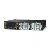
Bay 2- Configurable
1x100G or 3x40G
12Status LED2
USB 113Alarm LED’s3 , 4, and 5
USB 0Management Interface
LEDs
6 and 7
Management Interface15Link Status LED’s8
Micro-USB Console16Bay 0 - 8x 1/10 GE9
Console RJ-4517Bay 1 – 4x1/10 GE10
Figure 1: Cisco C8500-12X4QC Rear View
Power switch5Fans1
Power supply failure LED6Power supply input LED2
PEM 0, PEM 13 ,and 4
Link LED8Power LED
OFF - No power to
chassis.
Yellow - Power On, one
power supplyhas failed or
is not plugged in.
Green - All power is
within specifications
1
Management Interface
LED’s
L - Link LED - Off no
link, On Link is up.
S - Speed LED - One
blink 10Mbps, Two blinks
100Mbps, Three blinks
1000Mbps
9 and 10Status LED
OFF - System not booted
Red - System Failure
Yellow - System booted
to Rommon
Green - System Booted to
IOS
2
Cisco Catalyst 8500 Series Edge Platforms Hardware Installation Guide
3
Overview
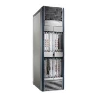
Front and Rear View Of Cisco C8500-12X4QC

 Loading...
