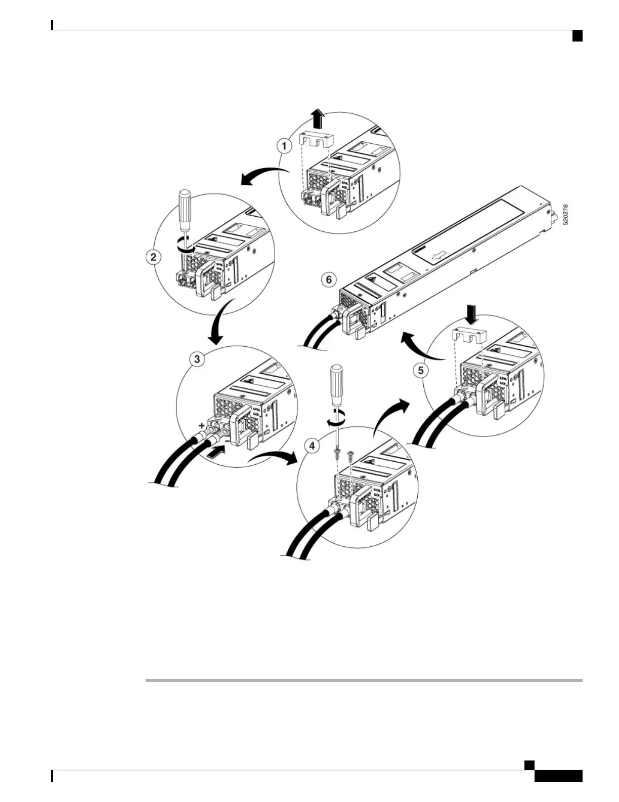
Figure 9: DC Power Supply Terminal Block Ground Cable Lugs
Step 4 Insert the stripped end of the wire into the open end of the lug.
Step 5 Crimp the wire in the barrel of the lug. Verify that the wire is securely attached to the lug.
Step 6 Place the wire against the terminal block, making sure there is solid metal to metal contact.
Step 7 Secure the lug to the chassis with two M4 screws. Ensure that the lug and the wire will not interfere with other
switch hardware or rack equipment.
Step 8 Replace the snap on cover on the terminal block of the DC power supply.
Cisco Catalyst 8500 Series Edge Platforms Hardware Installation Guide
41
Removing and Replacing FRUs
Wiring the DC Input Power Source
 Loading...


