• Top Cover Plate
• Top Cover
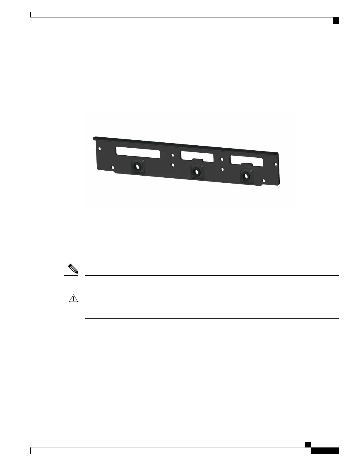
• Mounting Plate
• Bottom Cover
Figure 29: Back Cover Parts
The IP54 back cover ships as one piece with eight screws.
Installing the IP54 Kit
This section provides an overview of the IP54 kit installation.
Ensure that you are using proper static discharge techniques such as a wrist strap and static mat.
Note
Ensure the device is powered down before performing any removal or installation of a module.
Caution
Installing the Front Cover
The front cover of the IP54 kit is installed around the IR1800 using the four parts previously listed and the
screws provided.
Before you begin
Make sure all cables are removed and that the desired FRUs or blanks are installed before assembling the
front IP54 cover.
Cisco Catalyst IR1800 Rugged Series Router Hardware Installation Guide
71
Installing the IP54 Kit
Installing the IP54 Kit