Make sure both handles swing straight up. Use care not to bend the handles sideways.Caution
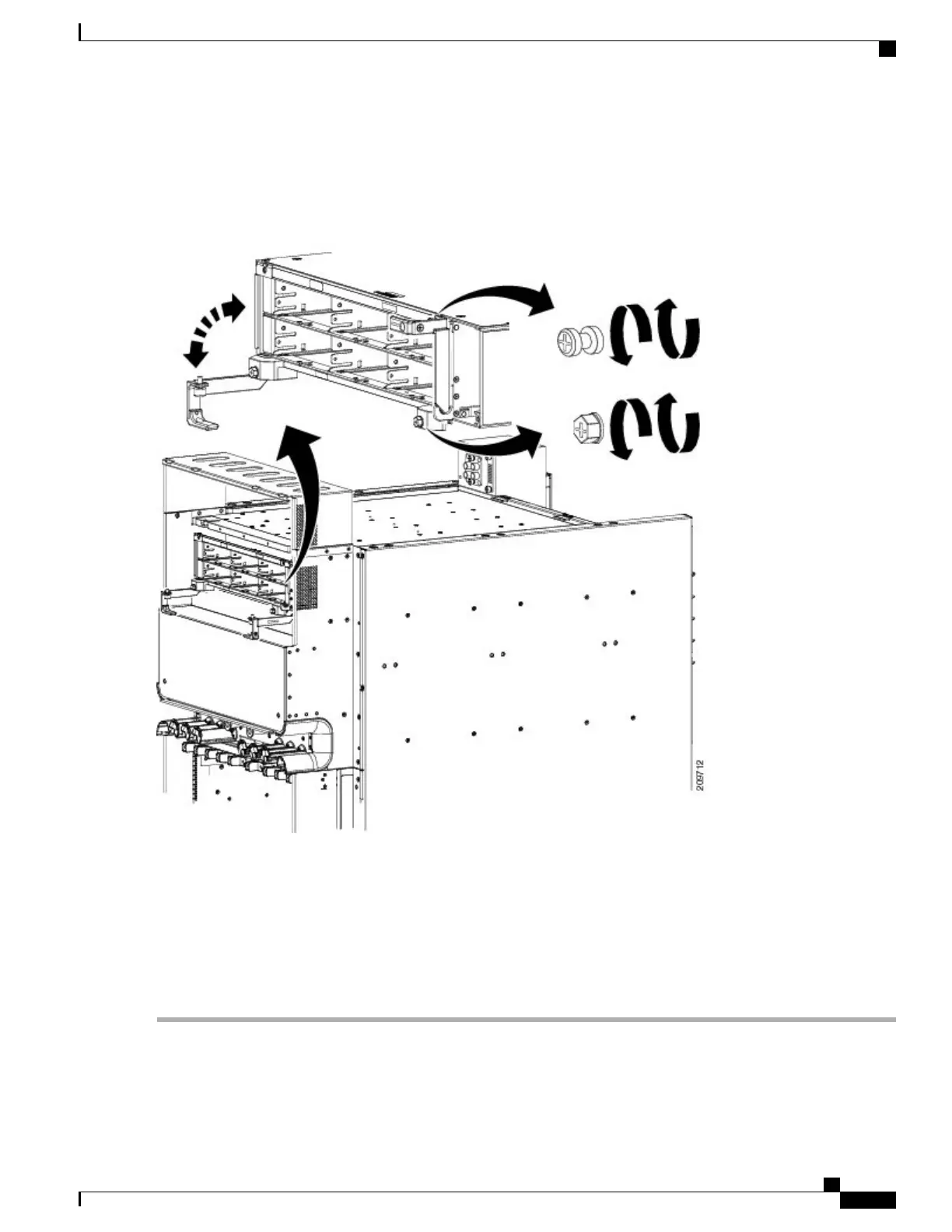
Figure 20: Installing and Securing Power Shelf
Step 5
Using the screwdriver, tighten the captive screw on both power shFigure 20: Installing and Securing Power Shelf, on
page 29 Figure 3-20 .
Step 6
Using the torque screwdriver, tighten the two screws that attach the bottom of the power shelf, one on each side, to the
chassis to a torque value of 15 in.-lb (1.69 N m) to 20 in.-lb (2.26 N m). See Figure 20: Installing and Securing Power
Shelf, on page 29.
The screws that secure the power shelf to the chassis are relied upon for power shelf bonding and grounding.Note
Step 7
Install the second power shelf, following through Step 3 through Step 6.
Cisco CRS Routers 16-Slot Line Card Chassis Enhanced Router Installation Guide
29
Installing Power Components
Installing an AC or DC Power Shelf
 Loading...


