chassis (left and right). You can also connect the ESD-preventive wrist strap leash to any bare metal surface on the
chassis.
Step 2
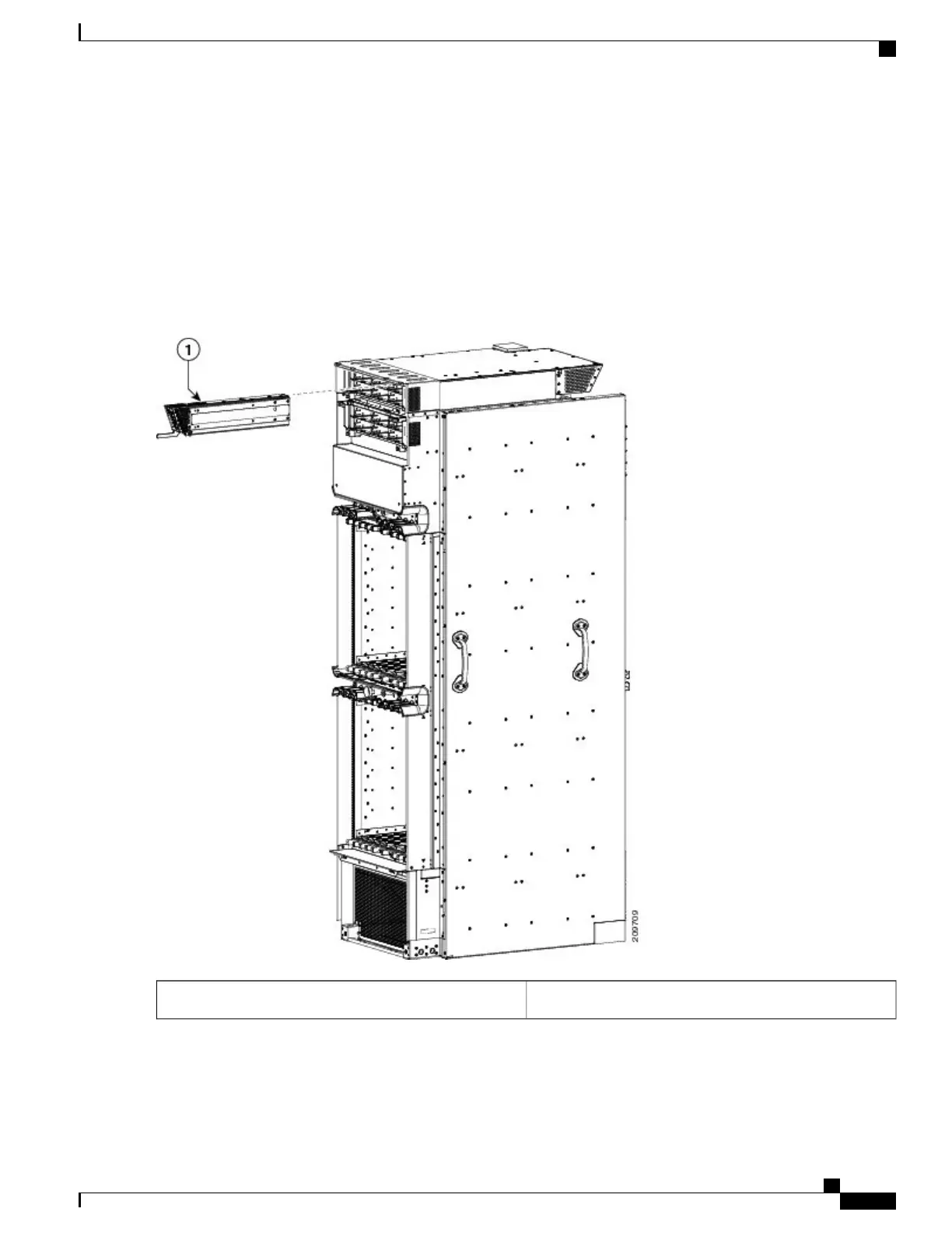
Hold the alarm module such that the ejector handle is on the lower left front side. See Figure 30: Installing Alarm Module
in Power Shelf, on page 43.
Step 3
Slide the alarm module into the bay on the right side of the power shelf. As you slide the module in, hold the ejector and
gently push until it engages the chassis. See Figure 30: Installing Alarm Module in Power Shelf, on page 43.
Figure 30: Installing Alarm Module in Power Shelf
Alarm module1
Cisco CRS Routers 16-Slot Line Card Chassis Enhanced Router Installation Guide
43
Installing Power Components
Installing an Alarm Module
 Loading...


