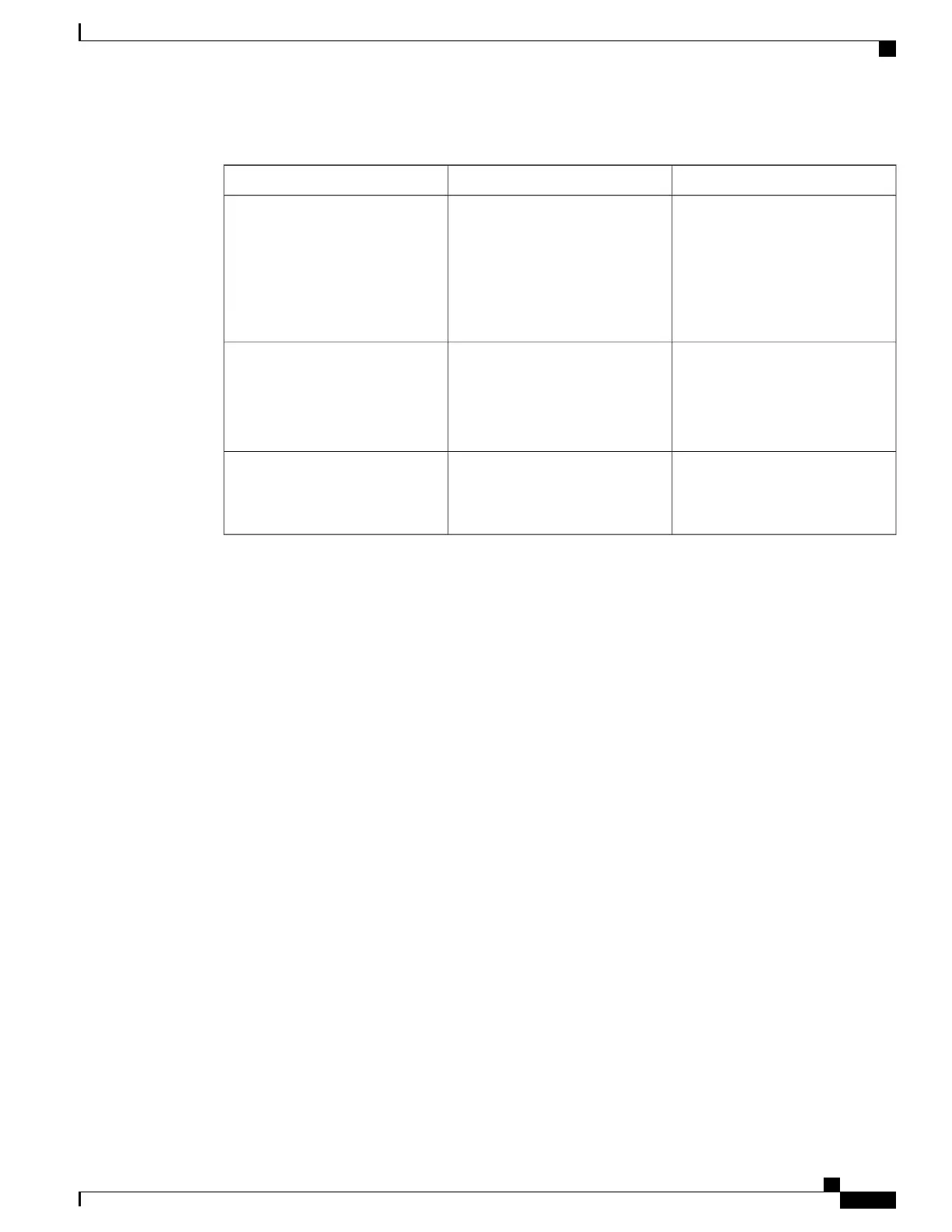
Table 2: PM LED Status Indicator LightS
Function or MeaningColorLED Name
On: The input voltage is present
and within regulation range.
Blinking: The input voltage is
present but out of regulation range.
Off: The input voltage is not
present.
GreenInput_OK
On: The output voltage is on.
Blinking: The PM is in a power
limit or an OC condition.
Off: The output voltage is off.
GreenOutput_OK
On: An internal fault is detected
within the PM.
Off: The PM has no internal fault.
RedInternal Fault
Power Up a Chassis
This section describes how to power up a chassis with AC or DC power shelves installed.
Prerequisites
Before performing this task, perform the following procedures:
If you have a DC power system installed, wiring at the BDFB or at the power plant should be complete.
Steps
To power on the chassis, perform the following steps:
Cisco CRS Routers 16-Slot Line Card Chassis Enhanced Router Installation Guide
51
Installing Power Components
Power Up a Chassis
 Loading...


