Power Up and Power Down a Chassis
This section describes how to power up and power down a chassis with an AC or DC power shelf. For details
on the chassis power systems, see the Basic Chassis Power Details, on page 1, the AC Power Systems, on
page 8, and the DC Power Systems, on page 6 . For complete information on regulatory compliance and
safety, see Regulatory Compliance and Safety Information for the Cisco CRS Carrier Routing System .
Most components on the chassis, such as the PMs, alarm modules, and fan trays, can be removed or installed
in the chassis while it is running. Although it is possible to install or remove a power shelf while the chassis
is running, it is recommended to remove power from the chassis completely, if possible, for service protection
and safety.
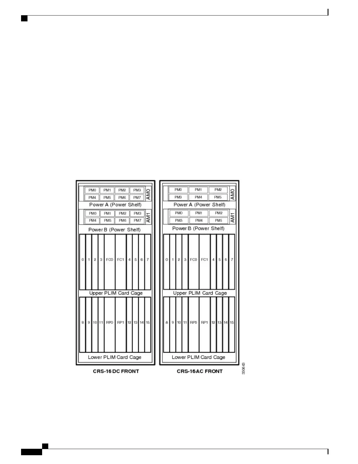
Figure 35: Cisco CRS Enhanced 16-Slot Line Card Chassis Front (PLIM) Side Slot Numbers, on page 50
shows the chassis slot number on the front (PLIM) side of the Cisco CRS Series Enhanced 16-slot Line Card
Chassis with an AC and DC power system installed.
Figure 35: Cisco CRS Enhanced 16-Slot Line Card Chassis Front (PLIM) Side Slot Numbers
Table 2: PM LED Status Indicator LightS, on page 51 shows the LED status indicator lights for the AC and
DC PMs in a power supply.
Cisco CRS Routers 16-Slot Line Card Chassis Enhanced Router Installation Guide
50
Installing Power Components
Power Up and Power Down a Chassis
 Loading...


