Figure 5: Input-Power-Present LEDS, on page 8 shows the input-power-present LEDs on the rear of the
DC power shelf.
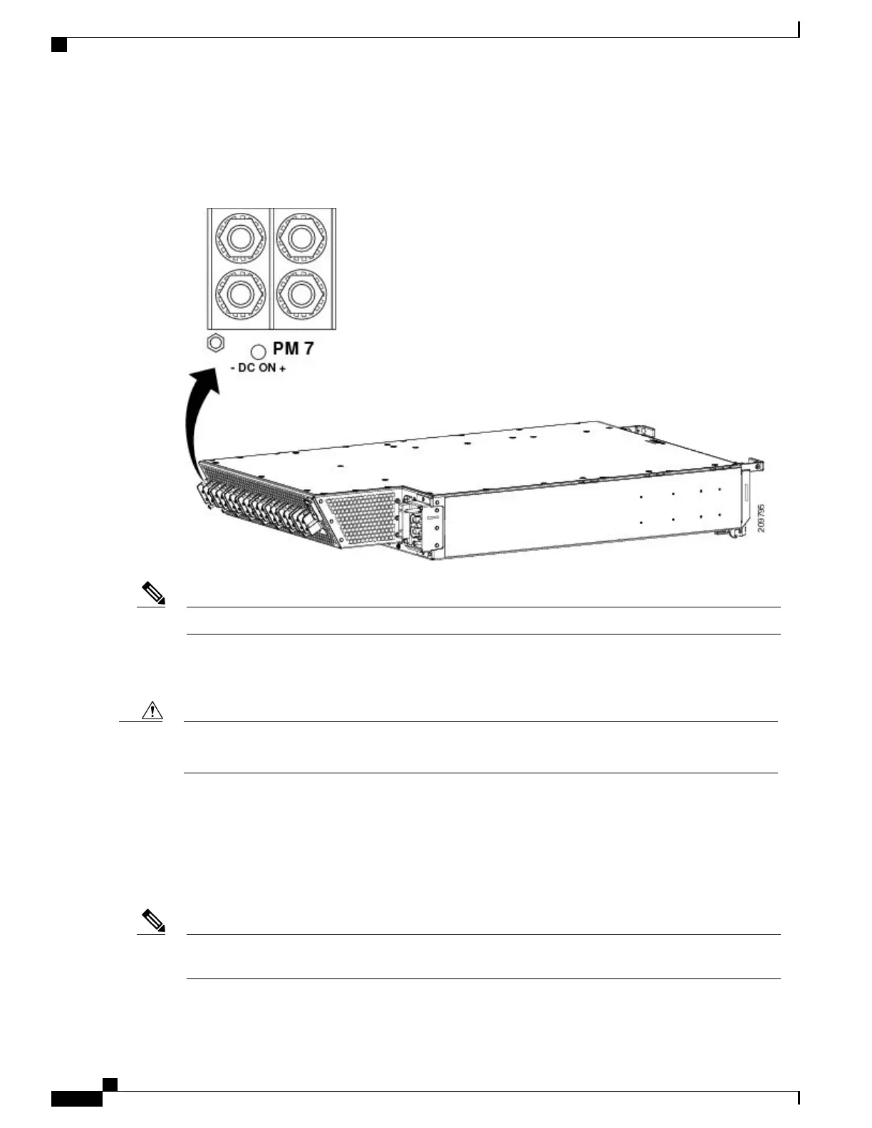
Figure 5: Input-Power-Present LEDS
Power should be disconnected before servicing the input power connection.Note
The input-power-present LED starts to light up when the input voltage reaches –20 VDC and the LED gets
brighter as voltage increases; the input-power-present LED is fully lit when the input voltage reaches –38
VDC.
If the input voltage polarity is reversed, or if the LED circuit fails, the LED will not light. When this is
the case, service personnel should check for hazardous voltages before working on the unit.
Caution
AC Power Systems
The Cisco CRS Series Enhanced 16-slot Line Card Chassis AC power system can provide up to 18,000 watts
to power the chassis. However, by default, the power capability of a system when shipped, with five AC PMs
per power shelf, is 15,000 watts.
Depending on the hardware deployed at your site, your system may not consume the maximum power
supplied by the power system.
Note
Cisco CRS Routers 16-Slot Line Card Chassis Enhanced Router Installation Guide
8
Installing Power Components
AC Power Systems
 Loading...


