Table 1: DC Input Current and Voltage Information
–48 VDC North America–60 VDC European
Community(range: –40 VDC to –72 VDC)
Nominal input voltage
50 A maximum at –48 VDC40 A maximum at –60
VDC60 A maximum at –40 VDC
Input line current
Each wiring block on the DC power shelf contains two sets of terminals, one positive and one negative, and
is covered by a plastic terminal block cover that is secured by a screw to a torque of 5 to 7 in.-lb (0.56 to 0.79
N-m). Each DC power cable is connected to the power shelf with a torque of 20 in.-lb (2.26 N-m). Maximum
wire size at the DC input terminal block is 2 AWG.
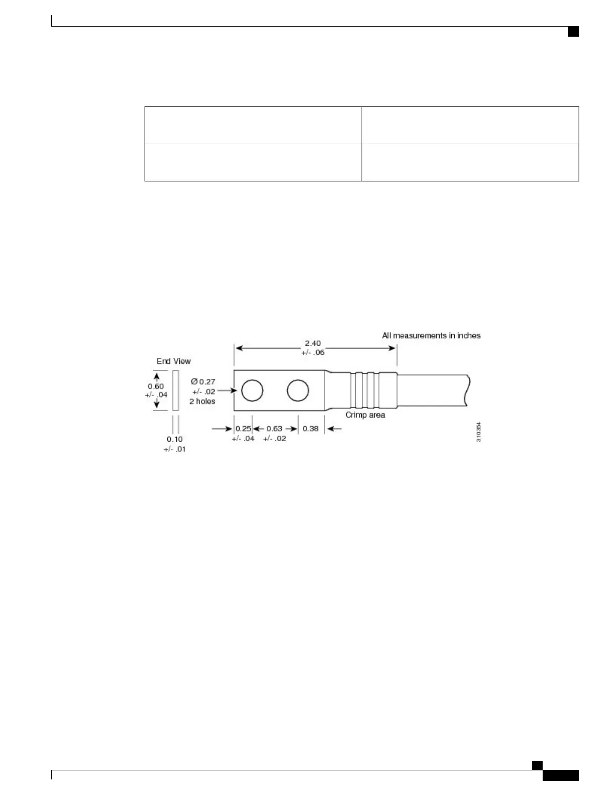
The power supply terminal posts are centered 0.63 inches (5/8 inch) (1.60 cm) apart and are M6-threaded.
We recommend that you use an appropriately sized 180-degree angle (straight) industry standard 2-hole,
standard barrel compression lug, as shown in Figure 4: DC Power Cable Lug, on page 7.
Figure 4: DC Power Cable Lug
For additional power details, see Appendix A, “Cisco CRS Series Carrier Routing System 16-Slot EC Line
Card Chassis Specifications” or the Cisco CRS Series Carrier Routing System 16-Slot Line Card Chassis
System Description .
Input-Power-Present LEDs
The DC input-power-present LEDs provide a visual indication to service personnel that there is voltage present
across the input terminal connection.
Cisco CRS Routers 16-Slot Line Card Chassis Enhanced Router Installation Guide
7
Installing Power Components
DC Power Systems
 Loading...


