chassis (left and right). You can also connect the ESD-preventive wrist strap leash to any bare metal surface on the
chassis.
Step 2
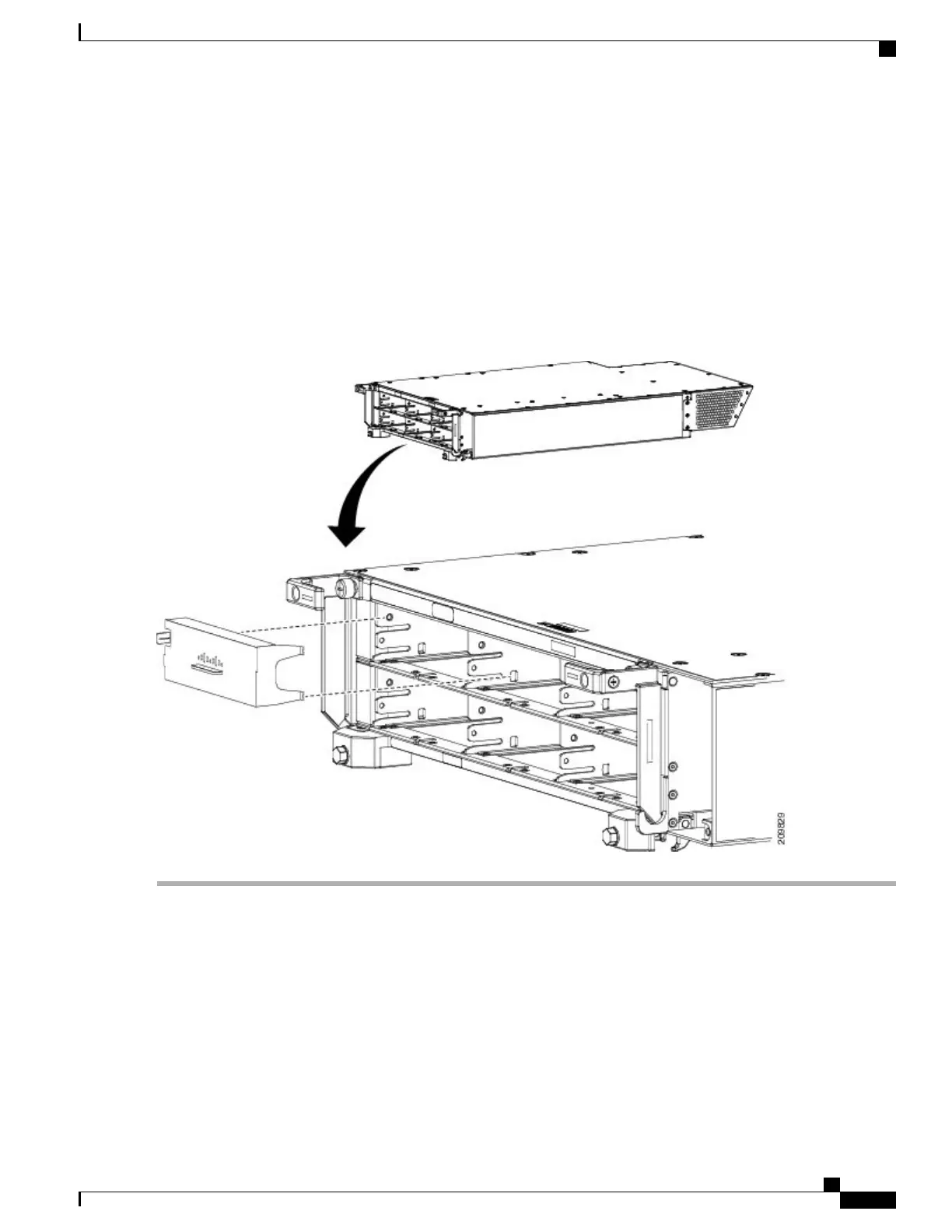
Align the PM slot cover with the empty PM slot in the power shelf.
Step 3
Insert the two tabs on the right side of the PM slot cover into the two holes on the right side of the PM slot. See Figure
34: Installing PM Slot Cover, on page 49.
Step 4
Push the left side of the PM slot cover gently until it clicks into place. See Figure 34: Installing PM Slot Cover, on page
49.
Figure 34: Installing PM Slot Cover
What to Do Next
After performing this task, re-install the upper grille on the front (PLIM) side of the chassis, if applicable.
Cisco CRS Routers 16-Slot Line Card Chassis Enhanced Router Installation Guide
49
Installing Power Components
Installing a Power Module Slot Cover
 Loading...


